Category: amateur radio

Radioddity GB2-D “Review”

I wanted an inexpensive DMR radio for one of my vehicles so somehow I ended up with the Radioddity DB25-D.  From what I saw it was about the best wattage for the least money once I shopped around and found it on a flash sale.  I paired the radio with an inexpensive Retevis antenna from amazon.

At the moment, my one word review is ….. “don’t.”  It’s a weird little radio with a particularly offensive “flaw” which I’ll discuss in a moment.  Otherwise, the purpose of use was to monitor my DMR repeater and to test its range in the area.  It seems as though it will suffice in that application.

So, “the issue.”  When I first set up the DMR talkgroups, I couldn’t hear anything come back – it was like the radio was muted.  But I could hear analog stations just fine.  Then I reset the radio, it set the radio to “promiscous” which is a DMR term for hearing all talk groups being broadcast by the repeated.  Which made the isssue more confusing.

What I finally determined was that unless you set an Rx group, you will hear nothing.  The solution is to create an Rx group for each talkgroup and then only add that talk group to the rx group.  It’s stupid and madness and not what the CPS guide says.

Another item on the list of complaints is though this is Radioddity’s radio and I bought it from them … it came with outdated firmware.

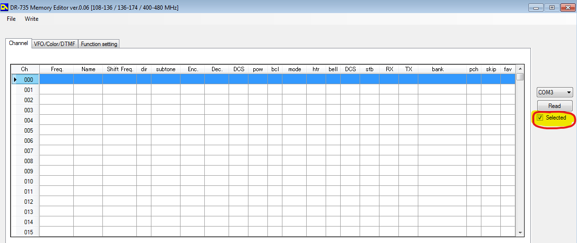
On to other issues: the CPS is windows only.  It’s possible to use MM7DBT’s codeplug editor in linux by using wine to run the program.  On Fedora 37 I also needed to install winetricks, then use winetricks to install dotnet47.  This will install the needed libraries and you can then run the codeplug editor.  The installer worked fine, but when attempting to run the codeplug editor I got a weird error about mono libraries.  Installing dotnet47 also install mono.

It looks like there’s ways to use serial ports in linux through wine, but a forum post led me to a python script that doesn’t work.  It’s definitely not the fault of @davidmpye as Radioddity has likely changed enough of the codeplug format so that it’s no longer compatible with the rt73.

I did find out that I can program on Fedora Linux with the Radioddity CPS.  First I needed to add myself to the dialout user group. Then I did the registry addition described here. Then, log out & in.

For posterity:

Configure the port–if the device is seen at /dev/ttyUSB0, and you want it to appear to WINE on COM1, edit HKEY_LOCAL_MACHINE\Software\Wine\Ports to have a new string entry named COM1 with value /dev/ttyUSB0

That’s all I have for now.


An Update. Not too notable.

Hrm, what to update on?  My last post was released roughly 4 months ago.  Who could have imagined where we would be today?  Corona is … mostly a ploy to destroy the economy in the wake of the November elections.  There are some real medical issues that could be present but its to the same group of people who are vulnerable to the seasonal flu.  Its time to get back to work America.

Having addressed that … what else is there to talk about?  Let me rummage about here.  This is more of a scrap bin update so … things might be rough in places.

Projects

The biggest change is that I have a new shop.  I would love to post pictures but operational security and all.  The new shop gives me better capabilities.  I’ve also expanded what tools I have on site.  A basic stick/tig welder, lathe, and work bench are all welcome additions to my capabilities.  I’m looking forward to starting my own business and maybe escaping from the nonsense that is corporate America.  My sales site is already listed on here, but for kicks, check out my offerings at underthebedstudio.com.

I also built a painting cabinet that helps keep the fumes down in the house and give excellent finishes to parts I need to paint.  One of the first projects that I used it for was a drive over antenna base.  My intention to use this at the remaining service events this year that don’t get cancelled as a result of the Panicdemic.

Another cool project I worked on was a Cigar Punch.  With my 3d printer I was able to iterate through designs pretty quickly.  I threw out the iterations but took a picture first:

Only took me 6 tries to get to the form factor I was happy with.  I also finally found a pre-hardened material to make the punch itself from (drill bushings), which was the cause of Mk4 & Mk 4.1.

While I was looking at a few things, I ended up buying an ESP-12s which I found prebuilt firmware that would let me use it as a serial port over wifi.  Pretty sweet.  So here’s my interpretation of it:

Here’s the Schematic for the protoboard above. It uses an 18650 cell under the board for powering everything. And here is the STL for the carrier. I used standard 8-32 screws to hold the protoboard down.  The charger circuit chip is here on Amazon.

Computer Jazz Hands

A few computer things that I’d like to talk about.

First up is the Retroflag GPi.  This is a pretty slick little box that takes a Raspberry Pi Zero (Wireless if that’s your thing) and turns it into a self contained Retropie gaming machine.  Being that its a Pi Zero, it struggles with anything over Super Nintendo but works pretty well for lots of other things.  If you’re into gaming I highly recommend it.  I just wish every single pi unit with the exception of the Pi3 wasn’t so damn finicky.  I do have scripts that allow me to turn off the wifi and the bluetooth and also rsync over wireless.  Code at the bottom.  One thing I would recommend to everyone – just get a bluetooth keyboard at the same time.  Normally I would recommend a 2.4ghz USB keyboard (I’m a fan of this one) but with the Pi Zero and the GPi case – bluetooth is best. I ended up with this one.

Ah, the Hak5 Jasager.  They released the firmware 2.4 for the Mark V a month or so ago.  I hate to say it, but I’ve never really gotten the thing to work as well as I would like.  I’m always fighting with it, and it seems to be always corrupting sd cards – which kills my plugins.  At this point, I would be hard pressed to buy the Mark VI.  Hak5, thanks for all you’ve taught me.  Best of wishes.

What about a Pwnagotchi?  A wifi auth key hacking tomagotchi?  Sweet.  But my dislike of RasPi’s still applies.  Also, its 2020 and now that I ponder the idea – I only see a couple of wifi configurations in the “wild.”  The first is with a proper WPA2 password which can be tricky to catch and crack.  The other is a captive portals with open associations.  And no, fortune 500 employers and authentication portal doesn’t secure the traffic of the users.  With open associations, no reason to associate.  Just grab it from the air.

I built myself a FreeNAS box last year as well.  This makes it super easy to back up my laptop across the network.  A few recommendations

  • Wire your network.  Seriously.  The speeds of a wired 10/100 easily exceed the speeds of wireless.  While you’re at it, this is an excellent time to learn how to make your own network cables.  Pick up a 100′ Cat5e cable and a crimpers + ends and go to town.  Custom length cables make management much easier.
  • Put in a “dumb” gigabit switch between your main computer and the freeNAS.  I bought this one, but I couldn’t tell you if it would better then any other.  Going to gigbit?  Amazing.  Most files get transferred before a status window can open.  And backups – ironically 10 times faster.
  • RAID.  RAID all the things!
  • And, do yourself a favor.  Get a cheap UPS to put the freeNAS on so minor (or major) power outages let it fail gracefully.
  • Having a well spec’d FreeNAS box lets you run servers all the time.  I have one that starts up to handle my DNS requests.  I’m running the Pi-Hole distribution because I’m not a fan of ads.  Or the tracking nonsense that they do.

Getting a FreeNAS box set up was awesome.  I highly recommend it.  Right now, I’m loving everything about it.

I’m still running Fedora 30 on my laptop.  I’ve never really booted to the Windows 10 installation that came with it – just to shrink the partition and I’m considering getting rid of it when I update to Fedora 32.  I’ve held out against Fedora 31 long enough that I think I’m going to wait for 32 now.  I usually do a fresh install.  To many things can get muddled when doing an update and a fresh start it always nice. Probably make an image of the HD again before I wipe Windows 10 though.  Shout out to Clonezilla.  Thanks guys!

Miscellaneous Topics

Affiliate Links.  There’s still no affiliate links here on the blog, and there will probably never, ever be unless the players change their tune.  As I figured, they’ve started to weaponize the Terms of Service and its just not worth it for the little money.  If the Youtube Adpocolypse can hit somebody like Demolition Ranch …. it will happen to anyone.  Free Speech is important – don’t let yourself get caught in the trap.  By the way, COVID-19 is totally Commie China’s fault.

Social Distancing.  Ugh.  Seriously?  Why did it take this for people to realize that door knobs, pin pads, and people are nasty?  They’re just nasty.  And, stay the hell out of my face.  COVID or not, I don’t want you within reach.  Just back off.  If you’re close enough that I could reach out and kick you … maybe you should back up just a touch.

Drones.  I would love to get a TinyWhoop with FPV.  I think it could be super useful and handy.  But then I look at my other drones that I never touch and convince myself its to much.  Drone guys, keep it up.  I’ll have to live vicariously through your youtube videos.

Macro Lens.  Why did I not buy one of these before?  They are super awesome.  I’ve messed with macro tubes, but they don’t work as well as a macro lense does.  I highly recommend buying refurbished lenses and flashes directly from Canon.  They’re a little more (like … $20) then what you would find for used prices, come with a warranty, and free shipping.  I’ve always been super happy with Canon equipment and their repair shop.  Seriously though, is this not gorgeous?  Having a macro lense is great for documenting any of the fiddly things I do, like below.  And honestly, I can see it being “one lense to rule them all” for me.  The kit lens is a close second.

I recently went through an purged my youtube subscriptions.  I think I got rid of half of them – many had been deleted or I no longer watched them.  A few channels to shout out:

  • Andrew Klavan – I love his satirical intros.
  • Marling Baits – He makes fishing baits, and good videos just to have playing.
  • This Old Tony – Dad Jokes and Machining.
  • AVE – irreverant as f*ck.
  • Ivan Miranda – massive scale 3d printing projects.
  • Project Binky – in Colour! Dry british humor, and the only car show I’ve ever liked.
  • Townsends – this man would have killed it on PBS when I was a kid.

The DS213 o-scope.  Not a bad little device.  Short on features, but for the price tag not a bad deal either.  It let me see some things I couldn’t see with my multimeter.  I have a proper oscope I need to repair, but to be honest I’m scared of the high voltage that’s inside.  I found a drybox case online that holds this and the probes perfectly.  Standard USB charging nonsense.

While I’m at it, check on the NanoVNA.  I’ve only really used it for checking SWR but there’s apparently a ton more that it can do.  Here’s my kit, with the adapters I’ll need to get it to work with my equipment.  As big as my go box and antenna setup is, its nice to know I can through this in my messenger bag or goruck with my laptop and be able to make some quick checks.  This does standard usb charging as well but it wants a USB-C cable but doesn’t implement the fast charging spec.  A waste.

Other Life Stuff

Still need to get digital working in my go box.  Hopefully taking the time this week to put my HF rig on a dummy load and do the experimenting that I need to do.

I could really use a vacation.  Somewhere tropical, sunny, and hot would be nice.  Maybe via a cruise ship?  Prices went through the floor now …..

Mentioning drones and how its not really something, I’d really love a Yaesu FT-818.  Oh well, I probably wouldn’t use that either.

In Closing

Rock on folks.  I’m going to peace out for a bit.  Hope you enjoyed the randomness presented above.

RetroPie Scripts

Make a folder in the RetroPie roms directory called “bash” – mkdir -r ~/RetroPie/roms/bash

Copy over bash scripts. I have scripts for enabling and disabling the wifi adaptor, as well as using rsync across my LAN for rom directory syncing

Copy bash-mod/configs/bash into /opt/retropie/configs/

Copy over bash-mod/theme/bash into /etc/emulationstation/themes/carbon (or whatever theme you’re running is)

sudo /etc/emulationstation/es_systems.cfg and add the following code to the <systemlist> tree:

						<system>
							<name>bash</name>
							<fullname>Bash Shell</fullname>
							<path>/home/pi/RetroPie/roms/bash</path>
							<extension>.sh .SH</extension>
							<command>/opt/retropie/supplementary/runcommand/runcommand.sh 0 _SYS_ bash %ROM%</command>
							<platform>bash</platform>
							<theme>bash</theme>
						</system>

Restart Emulation Station

bluetoothdown.sh

#!/bin/bash

sudo rfkill block bluetooth

bluetooth-up.sh

#!/bin/bash

sudo rfkill unblock bluetooth

wifi-down.sh

#!/bin/bash

#sudo ifconfig wlan0 down
sudo rfkill block wifi

wifi-up.sh

#!/bin/bash

#sudo ifconfig wlan0 up
sudo rfkill unblock wifi

Yet Another (Clever) End Fed: AKA The Slinky Antenna

My first antenna was a simple wire dipole that I carefully measured and built as a linked dipole system so I could work multiple bands (remember that an antenna at resonance both transmits and receives energy better then one “matched” with a tuner). My first solo field day, I found out how well dipoles work when tuning to a different band (they don’t) and how troublesome it could be to mess with an erected antenna (I improvised a mast, and then had to improvise get the legs of the dipole out).

The next antenna I built was based on the W4KGH end fed antenna.  Measure and cut wire, wound my first unun and then off I went with my go kit (a Yaesu 857d and MFJ-929 tuner with a cheap computer PSU to power the rig up) up to a friend’s cabin in Wisconsin. Hoisting this antenna was much easier as I only need one friendly tree and ended up with a basically a sloper antenna.  I was able to cross bands easily and heard a few people working the Colorado QSO Party over that Labor Day and tuned in a Number Station as well.

The end fed antenna was employed again at my Ham Club’s 2018 Field Day where I realized that the noise I thought was from my location in Wisconsin was likely from the power supply I was using. I also struggled to get it to tune on the lower bands. Hoisting was troublesome and while I had a friendly “tree,” I was barely able to get set up.

I’m a member of a Ham Radio Go Kits on Facebook, where a member posted of a slinky end fed on the group.  Using a slinky as a radiating element isn’t really new.  When I first started my journey as a ham, I ran across the Slinky Dipole and there was mention of the slinky endfed.  What appeals to me the most about the design is the “mast” that supports it.   A simple 20′ shore pole in the center of the coils of the slinky is all it takes

Credit where due

Due to the fact that I live in a HOA (the bane of hams) I can’t hoist an antenna permanently.  There’s also a dearth of the required “friendly trees” in the area.  I can get this antenna set up in under 10 minutes.  Tear down is 10 minutes as well.  This means I can spend more time operating then putting nonsense up in a tree.

This picture was taken before I had completed the mounting horn for the match box.  Before I talk about the design exhaustively, let’s talk real quick about how well the antenna does as far as SWR is concerned.  Ironically enough, the only portion of the band that this doesn’t need a tuner is for 2 meters!  Below is a table of 4 SWR sweeps of the antenna.  I swept the entire spectrum with a single single with and without a counterpoise and a double slinky (two slinkys I soldered together) again with and without a counterpoise.  Generally a single slinky without a counterpoise is the winner, except for a few flukes.  Overall, for field deployment I’ll bring a single slinky and the counterpoise but not bother to put it on.  For 40m and up, this generally presents less then 7:1 SWR.  If 80m is my goal, I’ll put the double slinky on and go.

Unlike my last two projects with picture ad nauseum, I’ve picked a small subset for your viewing pleasure. Here’s the CAD profile of the legs for the stand.  These were cut with a water jet from 14 gauge stainless steel.  The circles within the leg are to reduce the overall weight of the leg.  The notch at the base of the leg allows me to easily stake each of the feet.  Some would argue that its to heavy for the application, but the extra weight helps keep the antenna from tipping over without the stakes.  I think its a good balance.

The clamps that hold the legs to the shore pole are 3d printed – as are many other things within my ham radio world.  There’s some 3m double stick tape to keep them in place.

I designed the legs to pivot about the middle clamp so the top hole is drilled to provide clearance for the 8-32 bolt and lock nut that keep them in place.  The top and bottom clamp keep the legs in place.  For these clamps, the legs are tapped instead.  The leg flips to either the deployed position or stowed and an 8-32 bolt is threaded through.  This means that I don’t have to muck with a small fiddly nut in the field.Shot of the “clamps” being printed on my monoprice.   A few shots of the slinky.  One showing how the caps are attached to the slinky, and then a full profile of the single slinky and the double slinky.  I made small retaining straps using elastic and large buttons.  The wire coming out of the bottom is to connect the slinky to the match box.  I did the same sort of arrangement on both stacks of slinkies. Honestly, you don’t need to make it this complicated (in the video up top a simple lanyard clip is used but I always over complicated things. The matchbox.  The banana jacks ordered were to long and were almost touching each other.  I 3d printed some stand offs to try to clean this up.A shot of the mounting horn on the match box.
Found a neat spool on Thingiverse for the counterpoise wire (which per the above table isn’t generally needed).  Printed at 50% x & y, 75% z.


Shack-In-A-Box Mk2 Upgrades: Dimmable Lights, Fans, and Digital Comms

I came up with a few upgrades for my shack in a box:

  1. Integrate a set of Powerpoles into my Samlex power supply for a more aesthetically pleasing connection in the back.
  2. Add speed control/dimmer systems to the fans and lights so that I could control their intensity
  3. Mount my Signalink Digital Interface

These were all a result of working with the shack in a box over the last year. I was hoping to be done in time for the 2019 Field Day but with only one or two days on the weekends I wasn’t able to complete everything in time.  In my defense, the weatherman had predicted 2 days of thunderstorms straight, which is not quite agreeable to electrically charging long metal poles in the sky so I finished up my work on the shack in a box instead. The documentation below is roughly linear.

Build

Wire Guides, Redone

I knew the pwm modules I selected (more later) would require fitting a total of 10 new wires into the existing wire guides. The black ones designed in 2018 were filled to capacity, so I designed and printed some new ones. These were designed as two piece assemblies held together with #2-56 screws. By making the top removable, I saved myself recrimping all the spade connectors for the control panel as well as keeping having to keep the wires straight during reassembly.

Samlex SEC-1235 Anderson PowerPole Mod

Anderson Powerpoles are the defacto standard when it comes to amateur radio power connections.  My “main power feed” into my fused distribution box has powerpoles at the end.  This makes it easy to swap my “feed” between the on board Samlex SEC-1235 or off board batteries or other power sources.  Instead of the ugly “rat’s tail” I had rigged when I first mounted the power supply in November, I wanted to add integrated a set of powerpoles to the onboard Samlex SEC-1235 so it looked like it came that way from the factory.

Bah!

First, I opened up the samlex and pulled the guts out.  Since I would be cutting and filing, removing the internals completely was the easy way to make sure that nothing was fouled as a result. Hardened Power Systems offers the Anderson Autogrip. The idea is to press fit in the powerpoles and have a nice, clean presentation. I mounted them on the autogrip on the inside of the case to further clean the appearance.  The horizontal alignment was picked by finding a free space inside the case before I removed the circuit board and marking it with a sharpie.

After getting the powerpoles into the autogrips and then I reassembled everything and put it back in my mounting rack.  Originally, I intended for the samlex to tuck fully inside and under the bottom shelf.  However, I had some empty wire guides that stopped the samlex from being able to mount that deeply.  While I was swapping to the larger, two piece design I removed the additional wire guides I wasn’t using from the shelf.  This gave me the extra depth I needed to fit the samlex under the shelf, as deeply as I would have liked to originally.

Mounting the PWM Modules

The primary reason for pulling the shack in a box apart this year was to add a way to control the speed of the fans and the brightness of the lights.  I bought some bare PWM Modules from Amazon, knowing I could design and 3d print cases. The legs on the top hold the module down inside of the case.

The cases were designed to also mount the PWM modules to the bottom shelf with a pressed in 8-32 nut. I thought that I would need to hold the lids on with 4-40 screws and included the holes and nut mounts but later decided that the fit was tight enough that the 4-40’s were not needed.

Here is the cura rendering of the box and then lid.

Mounting these was a relatively simple affair, as was connecting the wiring.

Then I needed to mount the rheostats on the control panel for access. I placed some masking tape on the control panel, then put double sided tape on the knobs. I then test fit where the knobs looked the best, and I ended up centering them between the last switch and the USB outlets. I drilled two small 5/32 holes to mark where the knobs would be.

The 3/8″ plywood I used for the switch panel was actually as thick as the overall length of the thread and shaft for the rheostats.  To make it work, I drilled out the front side with a 1/2″ forstner bit.  I need to make some new knobs that would “hide” the deep 1/2″ hole I’d drilled.  A nice, chunky, friendly knob was designed. A small hole was added so that I could press in a small brass brad nail to indicate the position.  The size of the knob hides the 1/2″ hole I drilled, and has a shoulder that presses neatly onto the rheostat’s shaft.

Mounting the Signalink Mount

The last question was how to mount my signalink. I considered mounting it quite a few different ways but decided that I didn’t want to modify the case of the signalink in any way. So I elected to mount it from the face.

Mounting was tricky, but doable. I had to drill two new holes for the faceplate into the shelf. Then, I pushed the 8-32 screws I wanted to use into the bottom holes. The the screws and faceplate were then bolted onto the shelf. I removed the faceplate (and board) from the signalink. Then I pushed the case in from the back. I slid the faceplate and board back in. I printed this with pretty tight tolerances, so I had to push everything in square from all sides. I reattached the faceplate to the case, then used a set of 8-32 screws with washers to make sure that the signalink couldn’t push back on the front.  The faceplate sits on a small shoulder on the mount.

And here’s a demo of the lights and the fans.  I’ll demonstrate the Signalink in a later post.

Note: As before, I have chosen to provide many of the solid model STLs for the 3D Printed Parts I used. However, I provide these STLs without support. I may have suggestions or warnings but they are provided as is. I hope that they are useful to you, but they may not be. Free is free.

Parts

3d Printed

Ordered Parts


Alinco DR-735T: Programming On Linux Through Windows

In my previous post on my Alinco DR-735t, I configured Virtual Box to share my USB programming cable from the host to the VM.  Last night, while attempting to add some Amateur Satellites to my radio configuration I couldn’t get it to mount.  I’ve had bad luck with sharing USB devices through VirtualBox, probably because I’m doing something wrong.  At any rate, I found a post from TechToolTip that showed how to mount a host’s serial device within the virtual machine.  This worked flawlessly, and I feel will be a robust solution.  The only disadvantage is needing to shutdown the VM to configure the port sharing.  I still haven’t found a way to program the radio directly through linux, and I’m not hopeful that Alinco will support linux. For now though, using this feature of VirtualBox seems to work quite well.

Because I had lost the previous configuration, I cloned the radio to my Virtual Machine.  Similar to how you have to highlight all the channels you want to send, you have to highlight enough channels to clone your current configuration within the radio.  That is, unless, you uncheck the “selection” box, as shown below.  Then the program will read and write all memories, regardless of what you have selected – which I feel should be the default option.


Pistol Crossbow Antenna Launcher

Sometime around June 2017, I built an end fed antenna with match box. End feds are not … great antennas but they are decent for the space they take up in a go kit. The way mine is currently configured works well down to 40M. End feds are basically a long length of wire, with a 9:1 UNUN to help your tuner match it to multiple amatuer radio bands.

The real question though, is how to get the blasted thing up in a tree. Generally, the higher you can get an antenna, the better off you will be (unless you’re trying to do NVIS, but that’s a whole other subject). I considered using a modified spud gun, but I haven’t had good luck with spudguns in the past. I also didn’t like the idea of having to either hand pump the cannon or bring an air compressor. The NPOTA I attended we did not have an easy solution for powering a compressor either. So, here’s the solution I came up with.


Originally, I had been planning on mounting a fishing reel onto a slingshot and launching a lead weight with the slingshot.  However, I was at a local farm supply store and saw a Bolt Crossbow.  I thought it was a much better solution (and more accurate) then a slingshot and smaller then a bow & arrow, so I bought it.  I had gotten the zebco 202 on clearance at walmart that I was planning on mounting to a slingshot for getting ropes high in trees.  Since this crossbow can handle both purposes, I decided to use it for that.

Then, I had some layout and decisions to make.  I wanted to have two bolts on board the crossbow, and then the fishing reel.  With that information, I laid out how large a piece of 1×4 I needed.  I cut a channel with the table saw for the crossbow to fit in down the middle of the block, then drilled two holes in the block.  Then I drilled and tapped the crossbow to mount the block.  I drilled two holes to mount the fishing reel, then drilled and tapped the reel so I could mount the reel to the block.  Finally,  I drilled two holes on the opposite side of the reel for the bolts to fit in.  A hair tie (stolen from a sister) retains them.

All in all, a pretty simple build.  I keep toying with building another version, able to be taken down making it smaller and more compact, based on an ar15 pattern rifle.

Parts List:

Additional Resources


Shack-In-A-Box: Onboard Power

In a previous post, I documented the build process of my ham shack in a box.  Notably lacking was a power source to power the box, and this was something I decide that I would add and document in a later post.  Initially I though I would pull the server supply out of this box and mount it to finish out the calendar year, then purchase a solution like the Samlex closer to next year’s Field Day.  However, I decided instead of coming up with ways to mount two separate power supplies I would save myself the time and trouble and acquire the samlex supply this year.  There were issues with noise on the 80M band and I’m pretty sure the power supply was at fault.

After searching the current market offerings, I selected the Samlex Desktop Switching Power SEC-1235.

This power supply was selected because it was relatively featureless, and could provide 30 amps continuous, and 35A Peak.  With the onboard power monitoring and the way I intended to mount the supply, there was no need for the SEC-1235M model, which has its own onboard voltage and amperage display.

Samlex sells a mounting rack that allows you to mount a radio together with the power supply and I co-opted this idea for my mount. First, panels were drawn and a shop favor invoked for them to be cut on the water jet.  Then, I purchased keystock to mount the panels to, and to mount the power unit to the shack in a box.

Keystock drilled and tapped, panel holes cut & drilled

Keystock mounted. Need flat head screws for flush mounting.

Removing the factory screws and using original holes to mount the panels.

Another view of mounting the panels

Final Mounting

Another View

Fitted into the shack in a box


Shack-In-A-Box: Initial Build

What’s the point?

Go boxes exist across for a spectrum of purposes. Perhaps you have a sewing box, or a toolbox, or a box with everything required for D&D. By doing this, you have everything needed for that particular task and can be ready to go within a few moments notice – or not have to get everything collected for Friday’s game and you’re already late. Building a ham radio go box is no different – you can grab the unit, head out the door and and once on site have everything you need to operate.

I am primarily a portable operator (as a result of my HOA) who must set up each and every time. With a go box, having all my radios are mounted in a single portable box with the radio gear and power connections set up means I will have much longer to operate – and that much more isn’t left to chance.

I was inspired to build my go-box after joining the Ham Radio Go Box group on facebook. I ended up throwing my new 2m mobile in there as well as a result of starting to run my club’s monday night net. Here are pictures and remarks of the process.

What’s in the Box

Check out the for pictures. In the go-box, I have

  • HF + 2M/440 by the Yaesu 857d
  • MFJ 929 HF tuner connected to the Yaesu
  • 2m/440 + Crossbanding from the Alinco DR-735t
  • Built in illumination for dusk or after operations
  • Built in cooling for both radios
  • Onboard 120V power conversion and a power monitoring system for amp load and voltage (voltage is monitored on battery power)
  • USB Phone charging

Build Log

I drew an initial layout in cad to determine if I should purchase a 4u or 6u rackmount case. The rackmount system comes from the portable audio world and specifies a certain amount of space and a mounting system. Trying different variations, it was decided that a 6u box would provide for all the equipment I had currently, and some future expansion. I decided that purchasing a commercial rackmount would give me better results then building my own box as I have seen some do.

Ultimately, I selected the SKB 6U Roto Shallow Rack unit over a comparable Gator Box (or eurolite) for two reasons. The first was that the SKB features an internal gasket that while it won’t make the water proof, will certainly help keep out the spirit dampening rain storm. The second was that the SKB was better reviewed then any other rack mounts I had found. The additional sturdiness of the unit was worth the additional expense. I avoided the particle board solutions by Eurolite & Musician’s Friend due to the weight. Both the wood and plastic boxes are flight rated so there should be negligible difference in their durability with the weight of the poly boxes being at least half the weight of their wood equivalent. Radios & other things will make the box heavy enough on their own. Then, I needed to go from the vertical pillars of the rackmount system to a horizontal surface to mount the radios, tuner, and other gear. To rack them into the go-box, I ordered 1u racks from Navepoint. By ordering directly from Navepoint I saved about $2 each rack, exchanged an email for another $5 off, and still had free shipping. Much cheaper then purchasing from Amazon


I used the mounting brackets provided by yaesu and alinco for their radios. No reason to reinvent the wheel for a custom solution when what was provided works well. The radios were mounted in the slots in the navepoint shelves with the brackets that came with the radios from their manufacturers. You’ll note that at times the radio shelf is clamped a small masterforce vise. This method of keeping the shelf vertical to work on it works fairly well, especially when you let gravity work to your advantage. This is my go to method for handling the shelf when it is outside of the box.


A Blue Sea Systems 6 Circuit With Coverwas sourced from amazon. This helps protect the radios from short circuits with fusing, as well as providing a neat and clean way of distrubuting the power from whatever source I am using. I should note that its built with metric standards. Because of this, i found it a bit difficult to work with as I have minimal metric tooling. An initial fitting was done to make sure I was on course with the space requirements of everything so far. (I apologize for the potato phone pictures.)


Because of my desire to run the system from a battery, I ordered DC Shunt Monitoring System from amazon. I chose this particular model as opposed to the some of the meters around for its low draw – and that I can shut of the monitor and have no draw at all. The system displays the current voltage of power system, amps in use, watts, and watt hours. I needed a way to encapsulate the shunt, so I designed and 3d printed a shunt box that would allow me to mount the shunt in any orientation. The bottom of the shunt box has two hex hole for a 6-32 nuts to press in. The top has holes for 6-32 fasteners to fit through and tighten via the 6-32 nuts. The center hole is to bolt the shunt mount on the frame with a 1/4-20 bolt. STL below. There are tunnels for the main power wires and the display relay wires.


To mount the monitoring display, the power switches, and a USB charging port, I needed a small panel about the size of a 2u panel (3 1/2″ x 19″). The layout of the switches, power display, USB Charger, and control switches was mostly laid out on the fly. After layout, cutting, and test fits the board was sanded through to 400 grit and stained. Rustoleum Spray Lacquer was used as a protective coating. I found that laying the piece out horizontally and using heavy coats resulted in the best surface finish.

Each function of the box (such as the radios, the usb charging ports, the monitoring display) can be switched on individually. I sourced a number of 13.8 VDC 25A switches from Digikey instead of using lower amperage switches and relays – again with battery powered operation in mind. Because the switches were designed to be mounted in thin plastic, not plywood, I needed a way to engage the locking tabs on the switches on the board. Switch mounts were designed and 3d printed to engage the locking tabs on the switches and screw into the face of the board. The monitoring display was also made to be mounted in thin plastic or steel, so a frame for that was also designed and 3d-printed.


To keep the wiring neat and tidy as I run it to the switches, power supply, and more small wire mounts were designed and printed with my monoprice. An 8-32 nut is pressed into the slot, a #10 fender washer is placed in the top, and then it is bolted onto the tray with a 8-32 x 7/16″ machine screw for wires to run through. This helps keep the wiring tidy and supported.


Adding a feature I probably don’t need, stick-on LED tape was installed around front of the box. First the surface is prepped with isopropyl alcohol and then allowed to dry. The LED tape is applied, leaving the power leads in a supposedly convenient position. Deans Connectors were ordered to allow me to connect the switching panel to the LED tape. With these connectors installed, it becomes trivial to disconnect the lights from the switch board. High quality adhesive shrink tube was applied over the solder joints to protect against shorts.

After this, I began the final fit up and cable management of the wiring inside the case. This was fussy, test, trim, retest, retrim, crimp, retrim, install, remove work that consumed the better part of four days of work. Cable management is an important part of any job and I didn’t want wires hanging in loose bundles looking like garbage – hence printing and installing the wire mounts. Here you can just see the power feeds for the radio fitted over the top of the shelf. They are then fed down through the slots in the trays to each radio. Later, I realized that I needed to open up the slots as an powerpole can’t be pulled back through. Two of the ventilation slots were cut to form a generous slot to pass the powerpoles through. These were cut with a dremel, and then some hand filing to clean up the holes. I also needed to remove a section of the top rack on the side so that wires could pass out from behind the distribution box and make the required connections. Again, this was cut with a dremel and then hand filed.


I had to decide how to hook up the radios – whether I was going to use the factory connectors or powerpoles. I ended up with a mix of the two. I removed the alinco connector and switch the radio directly to Anderson Powerpoles. For my 857, I decided to keep the yaesu connector because of the brown wire (a stupid item imho but best to leave it). Powerpoles were installed on the drops, then a generous coating of dielectric grease was applied. I’ve read that powerpoles corrode quickly so this will help keep them from oxidizing without damaging the ability of power to flow across the tabs.


Axial fans were ordered to provide additional cooling to the radios. The fans from digikey were selected to to provide maximum airflow with a low 38.5dBA noise. If needed, I can mount a rheostat to slow the fans and lower the noise, at the cost of airflow. A fan mount was drawn in cad, and a shop favor called in for the panel to be cut with a water jet. Once it came back from the shop, a coat of rustoleum professional grade primer and then rustoleum gloss black was applied. I refuse to utilize krylon paints in my shop. I broke a fan blade just by tapping with with my finger, so I clearly needed to provide some protection to the fan blades. A fan cover mirroring the style of the grid on the fan mount was designed and printed. I reasoned that the fans could push no more air then they could pull, and mirrored the design of the fan mount. To save print time in the future, I redesigned the guards to have a sleeve and cover. While the sleeve adds slight complexity to the walls and increases their print time, it will save roughly 3 hours should I need to redesign or reprint from breakage the guard grid in the future. Here are the sleeves, and the first & second iteration of the guard. Printing with just shoulders pressing against the fan saves an hour of print time on the monoprice.

Small rubber grommets were ordered and 3/32 holes appropriate for the grommets were drilled. Grommets installed, the wires were passed through the side of the guard, and then wired in parallel to a deans connecter which was then hooked to the appropriate circuit. As will the led lighting, this makes it easier to service various parts of the box. The fans are attached with 6-32 bolts and acorn nuts for a finished look. The fans pull air from the rear of the case and push it towards the front. The user of the go-box experiences a slight breeze.


A “rack” of sorts was designed and printed for the MFJ-929 HF Tuner paired with my Yaesu 857d. This rack barely fit on my monoprice – I had to set the bed size to 121mm x 121mm and get rid of the brim to print these. Taking advantage of rapid iteration through 3d printing, here is the mark 2 version of the tuner mount mount, which loses a mounting hole on the base, and eliminated the need to drill and tap the side of my tuner as I had originally planned. A slot that fits to the center screw on the side of the tuner helps center & retain the tuner in these mounts. Then, a sliding armature was designed that will insure the vertical retention of the tuner.

With the initially printed arms, I had issues with the print warping, and the arms tilting back. I lost some faith in the retention ability of the arms because of this. I initially planned on printing the arms in a way that they couldn’t warp from heat differences as the layers were applied. I changed from the initial arm design to Mk 2.5 to help reduce the print time, and to make things look nicer. After a test print with the arm at about 15° on the print bed I decided I didn’t like the results when I cleaned up the print. So instead, I printed two more arms, gently heated the pla prints, then pressed down with a wood slat to intentionally warp the print so that when bolted onto the mounts, they would squeeze down and against the print. Mk 1 & Mk 2 below.

The fan panel makes it harder to get to the pl-259 jacks on the back of the radios. To make it easier, I ordered and installed some right angle adapters to the radios. The 857 was connected to the tuner with a cable that has a right angle connector.


Closing Thoughts

At this point, I’m posting the build log. I will have to make a few updates for things such as integral power supply, hand mic mounts, and the smaller 2M antenna I’m building to keep in the go-box for deployments. However, the go-box itself is practically done.


There are a few things I will do differently for the next build. I would have a smaller switching section. The parasitic draw of the radios is not enough to justify the cost & trouble. If I was doing a SOTA where I had to hill climb for this, I would take a Yaesu FT-817nd or Yaesu FT-818. Still, for this box I think it all works well and I am in no hurry to tear everything apart to make Mark 2. Even though this is less of a go-box and more of a shack in a box I’m satisfied with the result.

Gallery

Go Box at Field Day

The go-box’s first deployment was the ARRL’s 2018 Field Day. Note that the tuner is retained by string and that the power supply is external. I simply ran out of time to get everything done.

Operated with my W4KGH End Fed Antenna (Doc 1, Doc 2) with 9:1 Unun, 55’ radiator & counterpoise. Worked well on 40M. 80M was barely able to tune. The noise floor for 80M was S5-S9 though so I was unable to hear anyone.


Random At The Bench

I had an issue with the amperage display reading incorrectly. Here I am verify the wire and testing its reading against my fluke 87V.


Parts

Ordered Parts

  1. SKB 6u Shallow Rack
  2. Blue Sea Systems ST Blade Fuse Block
  3. NavePoint 1U Racks
  4. Switches
  5. PowerSupply
  6. DC Shunt Monitor
  7. 12V Warm White LED Strip Lights
  8. 18 Gauge Stranded Hookup Wire, White
  9. 18 Gauge Stranded Hookup Wire, Black
  10. Deans Connectors
  11. Shrink Tubings
  12. Case Fans
  13. 90° PL-259 to straight PL-259 cable
  14. 90° UHF adapters
  15. Rubber Grommets

Printed Parts

Note: I have chosen to provide many of the solid model STLs for the 3D Printed Parts I used. 3D Printing is an incredible technology, and I amazed to be able to use it so easily. However, I provide these STLs without support. I may have suggestions or warnings but they are provided as is. I hope that they are useful to you, but they may not be.

  1. Switch Plates
  2. Wire Guides. Note – max capacity is 4 12 gauge automotive wires. A 8-32 x 7/16″ bolt will rack these perfectly with no interference to the wires with a .050″ fender washer and a 14 gauge steel shelf.
  3. DC Shunt Box STL’s
  4. Fan Sleeve
  5. Fan Cover
  6. Tuner Mounting Fixtures

Creative Commons License
These STL’s are licensed under a Creative Commons Attribution-NonCommercial-NoDerivatives 4.0 International License. I do not certify anything other then loosing your beer money over these. They may or may not be useful. Remember, only Hu can Prevent Florist Friars!


Alinco DR-735T: Initial Thoughts

I recently purchased a new VHF\UHF radio. I intend to purchase 2 of the same radios, one of which will reside in my go-box and one which will be installed in my new car (that I do not own yet). One of the things that attracted me to the was the crossbanding feature.  Another was that it was not yaesu\icom.

Another one of the things that attracted me to the Alinco’s DR-735 Clone Utility was the programming software … which is actually terrible and undocumented. I’m going to relate a few things about the programming software as I haven’t seen any documentation.  Hopefully this will help someone having a bonehead day.

First – it requires .Net 4.5 which is happily installs … with a japanese installer.  Good thing we just keep clicking next right?  Ugh.  But it does actually install, and run.

Configuring channels is hard – let’s export from my CHIRP config and remix that to import as the clone utility.  But … it appears that the cvs import is broken.  I received strange errors like “Subtone NG : Line=3” until I managed to craft a CVS file that the program was happy with:

Once I was able to edit my cvs file to match the exported format from the software, … I was barely able to import simplex channels. I could not load repeaters from the cvs file (even one that was exported by the software itself). I don’t understand the problem and ended up putting in the first memory manually. Copy/paste does work though, so once you struggle through setting up the first repeater you can copy\paste and then edit the rest:

But here’s what really screwed me up (for to long).  If you’re working on a smaller computer, like a netbook you’ll get a cryptic error message.  If you’ve worked serial ports before you’ll instinctively know what the problem is.   Until you get a larger screen though, you won’t be able to do anything about it.  Here’s from a VM shrunk down:

And here’s from a VM that I left at the full 1920×1080 of my new computer:
You’ll notice off in the right hand side a dropdown saying “COM3.”  Yes, that’s right.  You lose the option to configure the com port the clone software expects to use!   Once I tried a bigger monitor (for some reason the external display on my netbook goes to 1280) I was able to select the proper COM port and then only upload the first channel of my config.  Turns out you have to select all the channels you want to upload.

In my mind, the com port selection should be with the File\Write menus, not where it can get lost.  I can understand the CVS import failing (to an extent).  But a properly crafted CVS, or indeed, one exported by the program itself should import more then just the simplex options in the config.

I have to give the clone utility 1 star since it seems mostly broken.  How does the radio follow suite?  Suffice it to say I am glad I did not buy 2 from the start.  I look forward to the radio functioning well enough that I have no reservations about buying a second.


AAR: Pumpkin Fest

On October, I helped out my local ham club doing background logistics for the floats in the Pumpkin Fest Parade.  Our job was to get the floats out in the order they should be, monitor the progress of the floats through the parade, and radio if something went south.  Pretty interesting work, if a bit boring.  If you get the chance you should definitely help out your local club with a parade.

Here is my “kombat rig” that I wore while helping out.

img_3073-jpg-convert

The list of things I’d do differently is pretty short. I’d dress a bit warmer. I’ll also wear my electronic muffs. I wasn’t thrilled about cutting off my hearing entirely – if something happens I want to hear. But if the noise gets to loud it will cut off. And I should have packed some snackage to munch on once the parade got started.

Previously I had used a back pack. It worked, but it was really over kill for the situations I have worked. My car is always within walking distance, so now I prefer this super simple, light weight rig. I will be adding this radio carrier to the mix.

Parts from left to right:

  • Dump pouch
  • Organizing pouch, good for holding maps and a spare battery for your radio.
  • Baofeng Radio setup:
    • Signal Stuff Antenna. My antenna and radio are setup for BNC.
    • Baofeng BF-F8HP radio
    • Extended battery. The 8 watts really drains the stock battery. Keep it for a spare.
    • A Handset. I’ve goofed around with the throat mics, and honestly these are the best no muss solution. Quality control it yourself and make sure everything works before you hit the field, or you’ll do my screw all over again.
    • Acoustic Tube. You definitely should be using an acoustic tube so you can actually hear the communications over the din of the crowd.
  • A few nondescript carabiners for attaching things to. I had my drinking bottle clasped to my belt as well as my volunteer flag.
  • An earplug for the other ear. The noise of the crowd started to mess with me and put me into sensory overload. Not fun, and not acceptable when working an event. Additionally, when a 100 year old steam engine whistle goes off 5 feet in front of you, you’ll appreciate the lowly ear plug..