Category: go box

Yet Another (Clever) End Fed: AKA The Slinky Antenna

My first antenna was a simple wire dipole that I carefully measured and built as a linked dipole system so I could work multiple bands (remember that an antenna at resonance both transmits and receives energy better then one “matched” with a tuner). My first solo field day, I found out how well dipoles work when tuning to a different band (they don’t) and how troublesome it could be to mess with an erected antenna (I improvised a mast, and then had to improvise get the legs of the dipole out).

The next antenna I built was based on the W4KGH end fed antenna.  Measure and cut wire, wound my first unun and then off I went with my go kit (a Yaesu 857d and MFJ-929 tuner with a cheap computer PSU to power the rig up) up to a friend’s cabin in Wisconsin. Hoisting this antenna was much easier as I only need one friendly tree and ended up with a basically a sloper antenna.  I was able to cross bands easily and heard a few people working the Colorado QSO Party over that Labor Day and tuned in a Number Station as well.

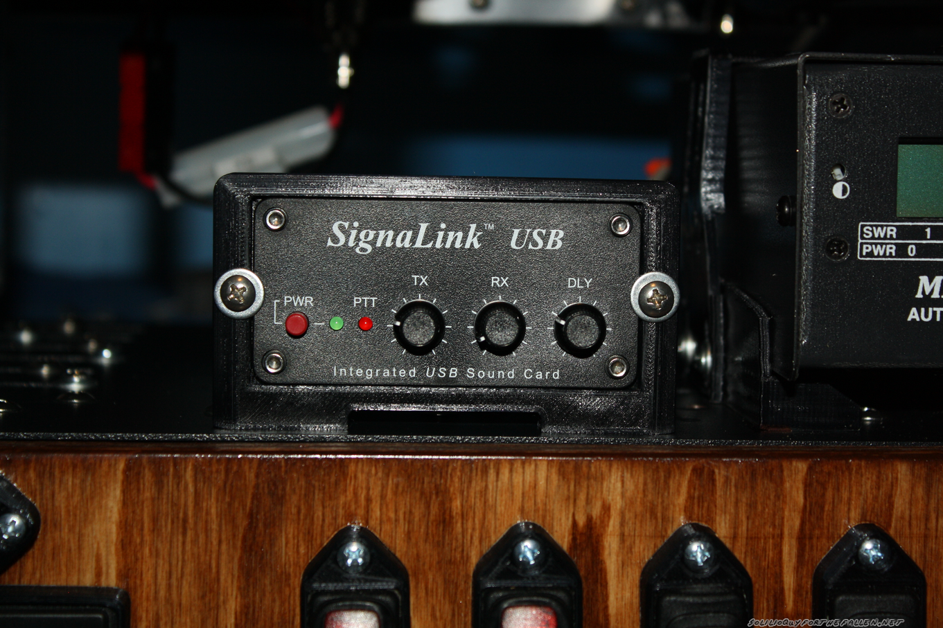
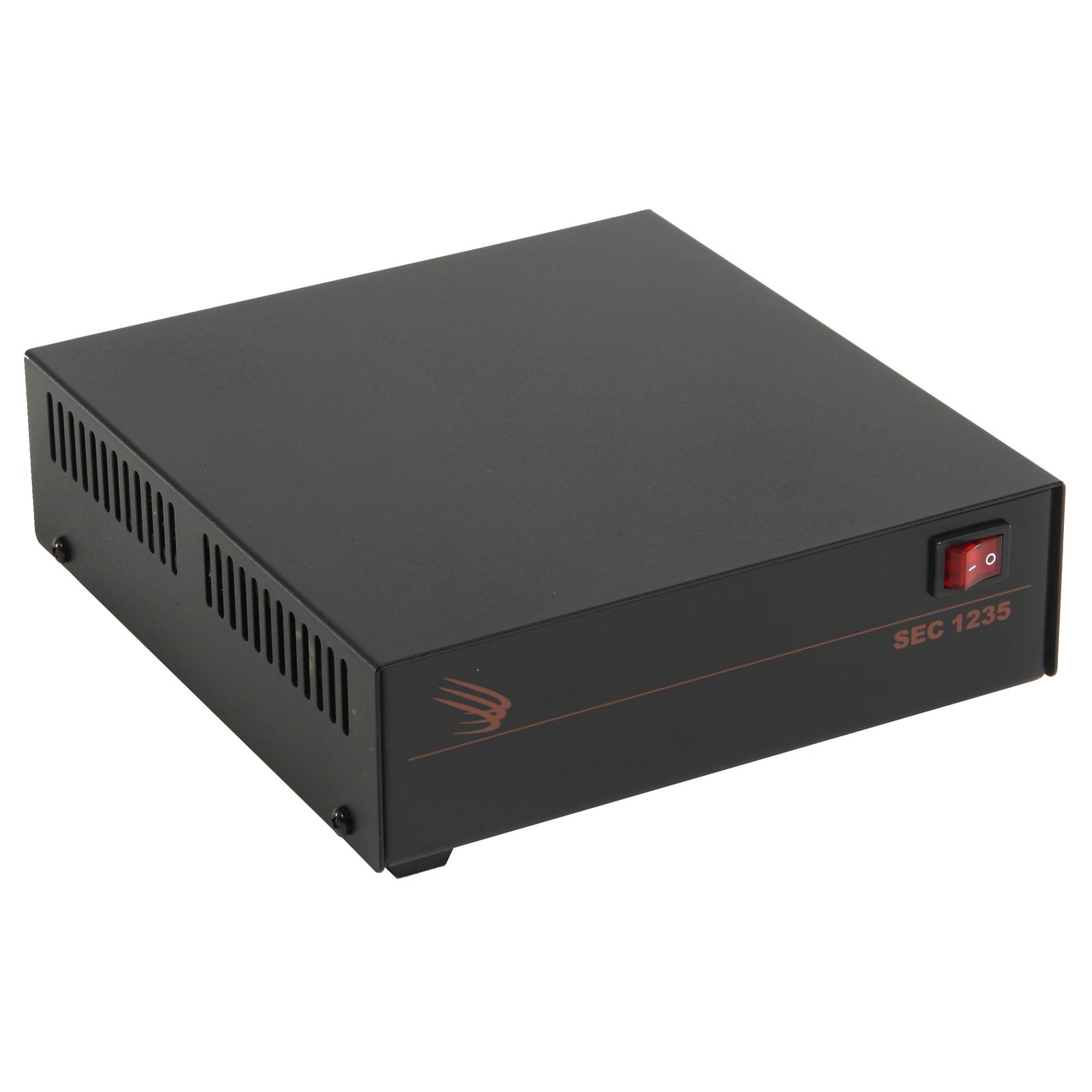
The end fed antenna was employed again at my Ham Club’s 2018 Field Day where I realized that the noise I thought was from my location in Wisconsin was likely from the power supply I was using. I also struggled to get it to tune on the lower bands. Hoisting was troublesome and while I had a friendly “tree,” I was barely able to get set up.

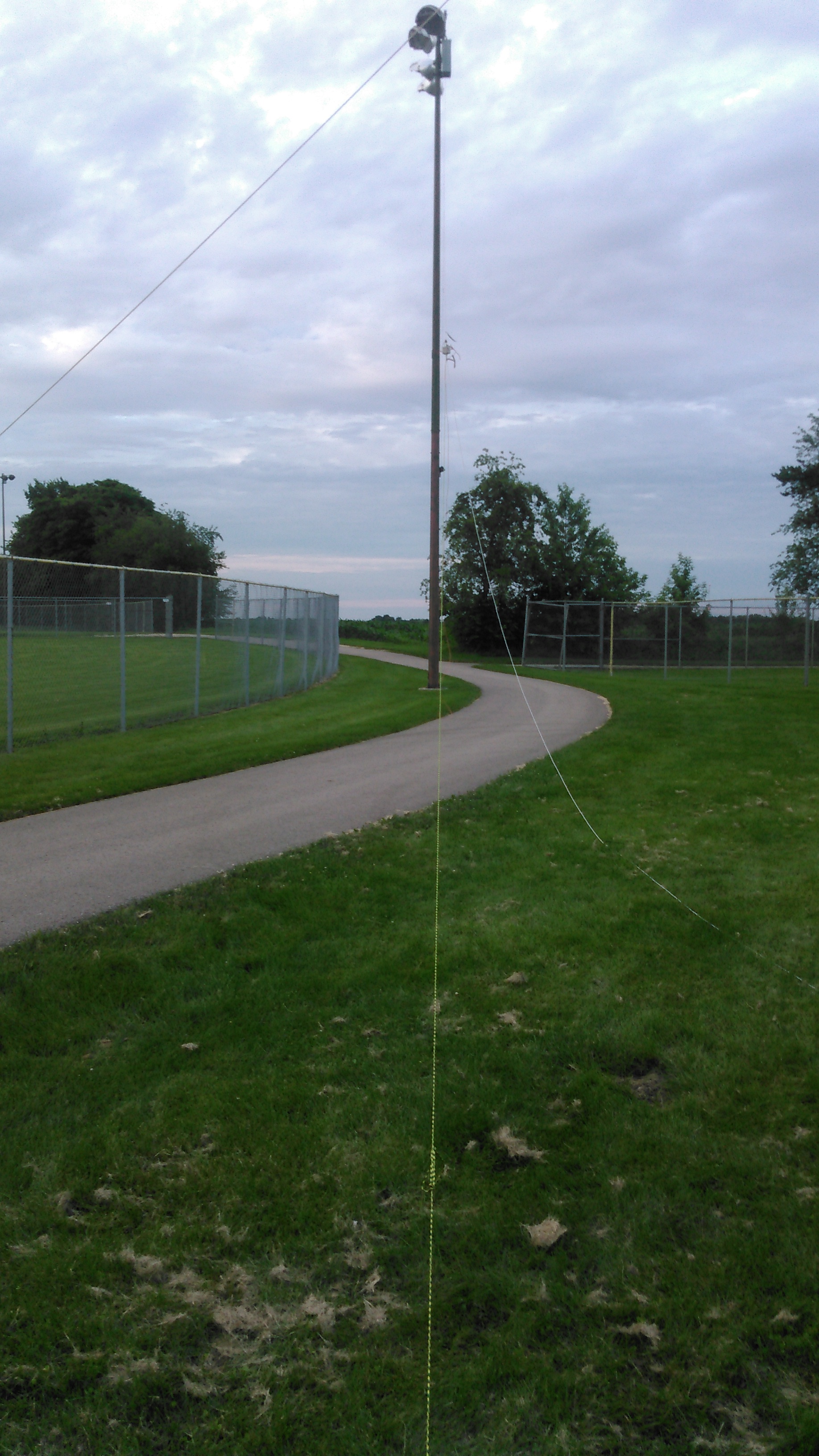
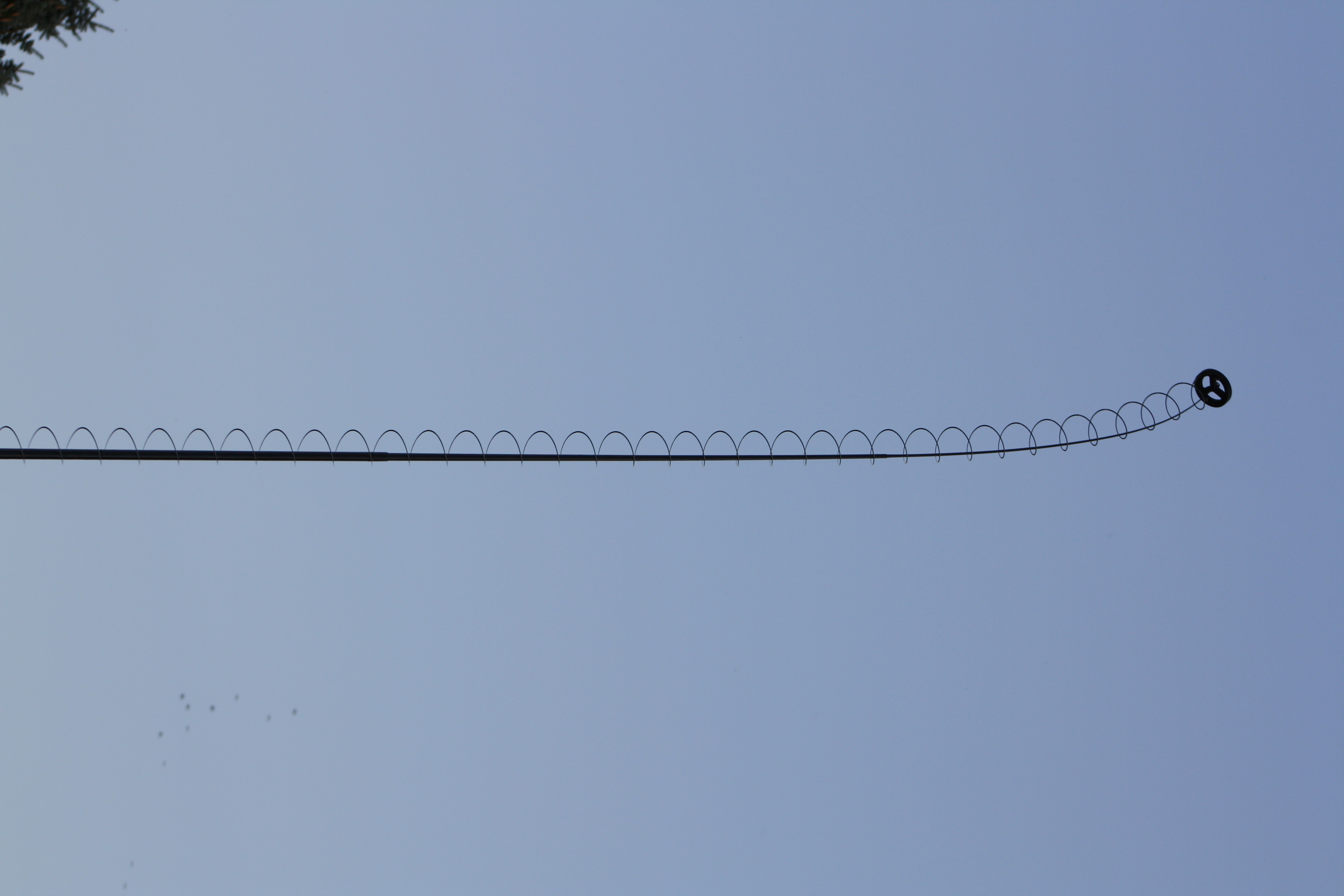
I’m a member of a Ham Radio Go Kits on Facebook, where a member posted of a slinky end fed on the group.  Using a slinky as a radiating element isn’t really new.  When I first started my journey as a ham, I ran across the Slinky Dipole and there was mention of the slinky endfed.  What appeals to me the most about the design is the “mast” that supports it.   A simple 20′ shore pole in the center of the coils of the slinky is all it takes

Credit where due

Due to the fact that I live in a HOA (the bane of hams) I can’t hoist an antenna permanently.  There’s also a dearth of the required “friendly trees” in the area.  I can get this antenna set up in under 10 minutes.  Tear down is 10 minutes as well.  This means I can spend more time operating then putting nonsense up in a tree.

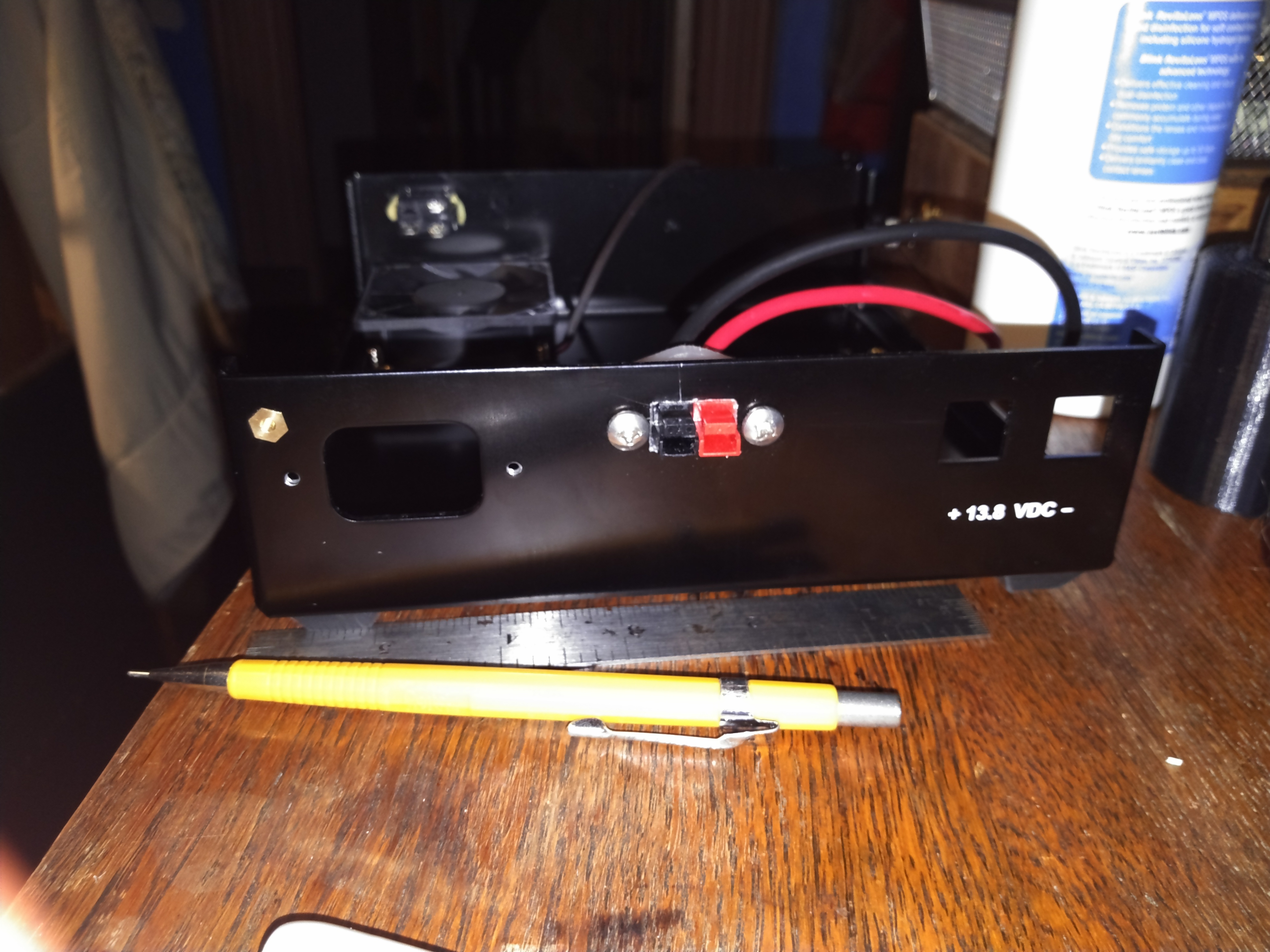
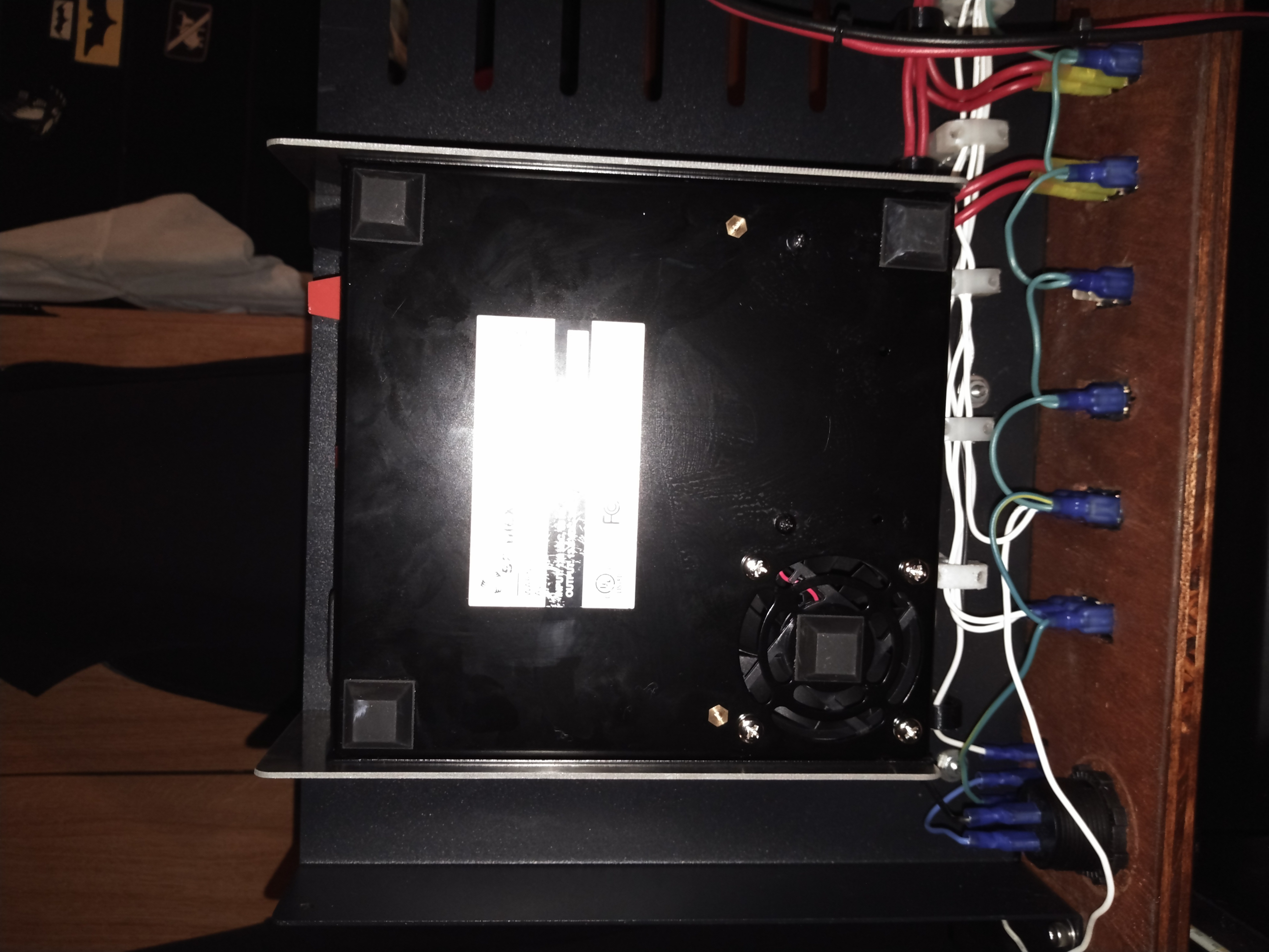
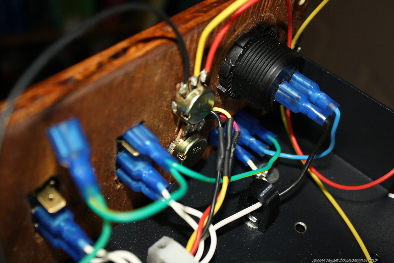
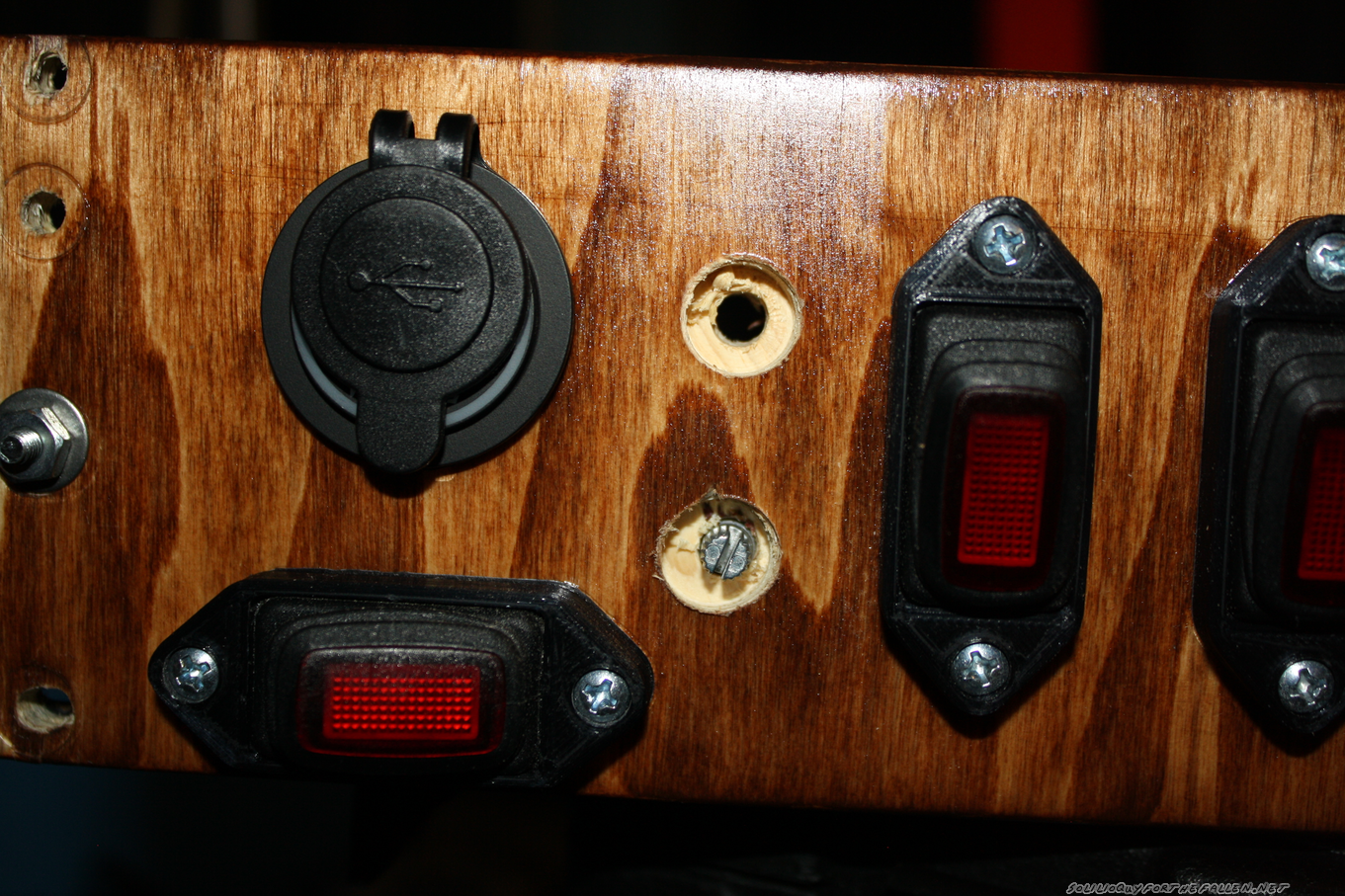
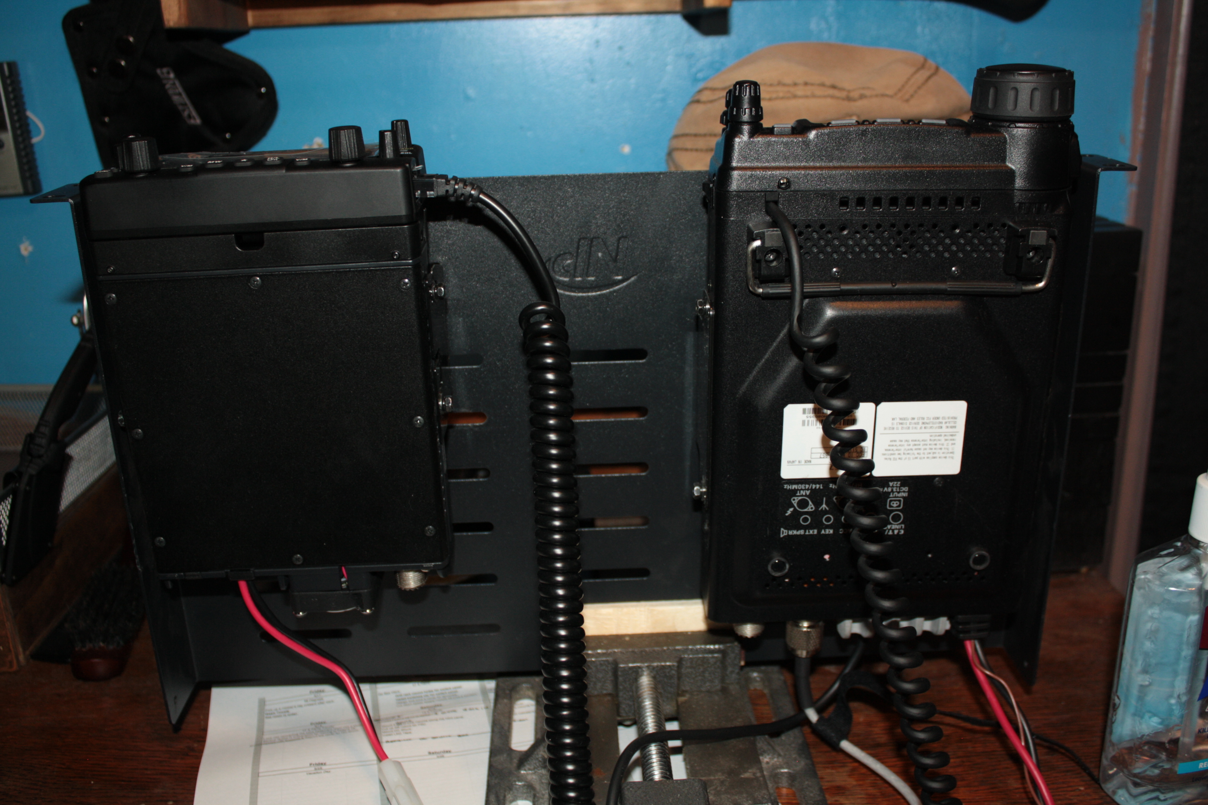
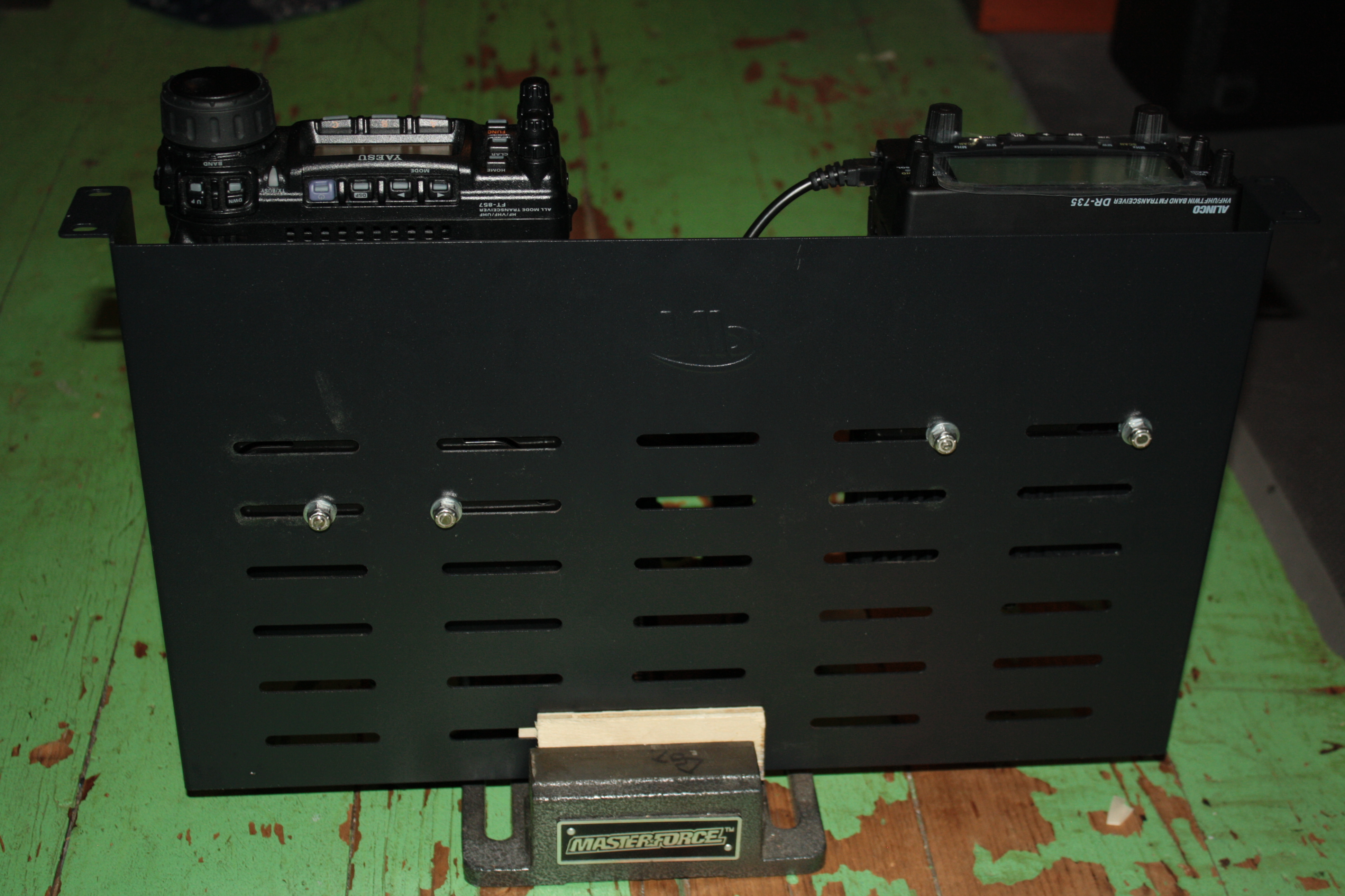
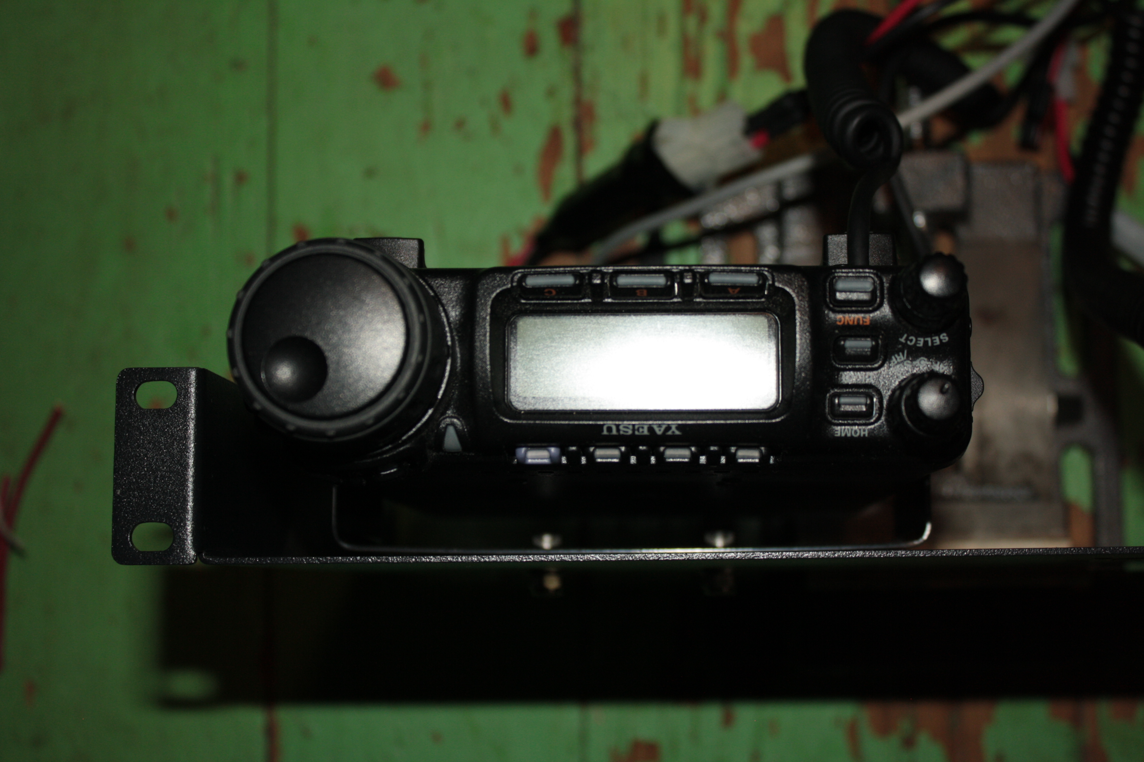
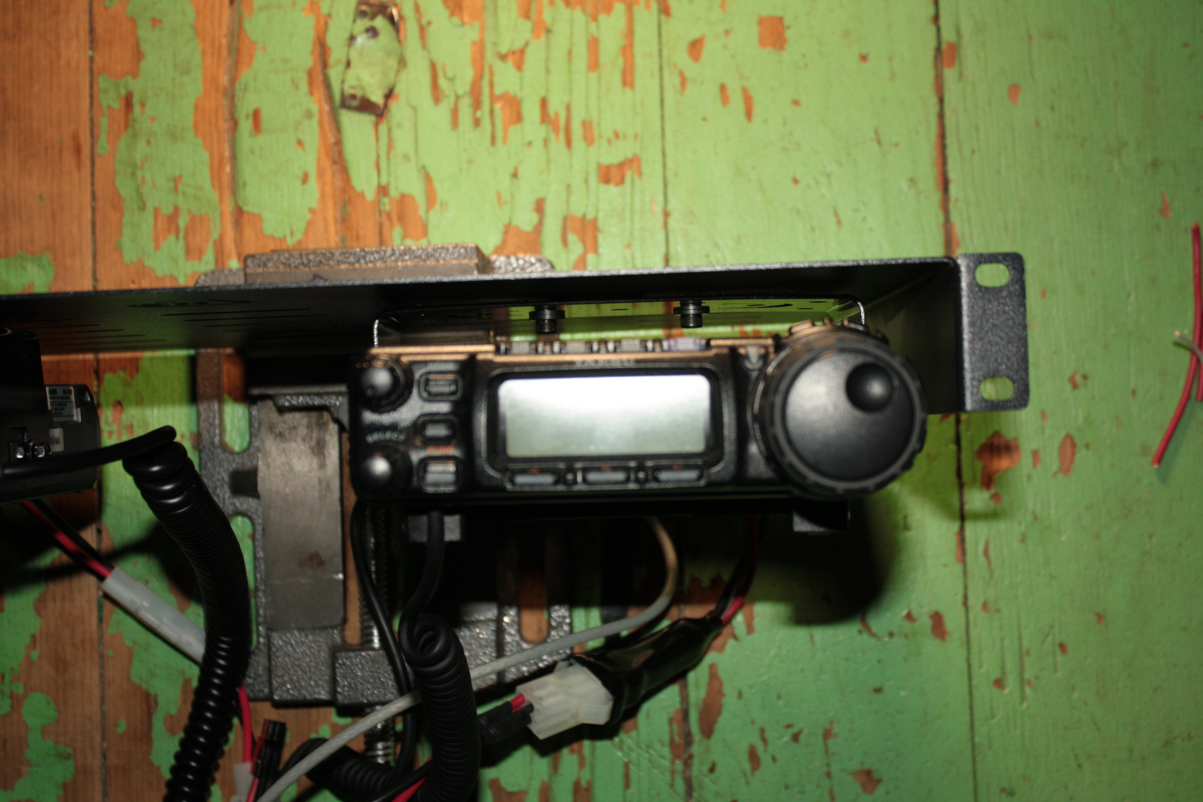
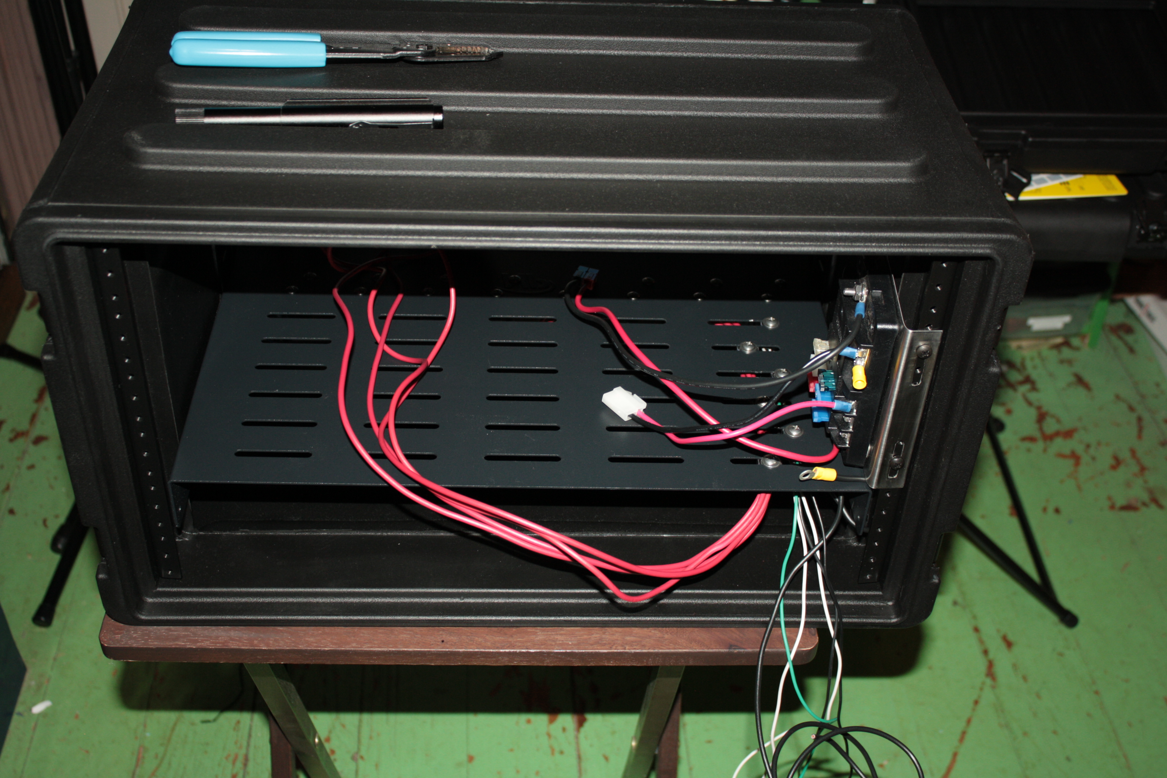
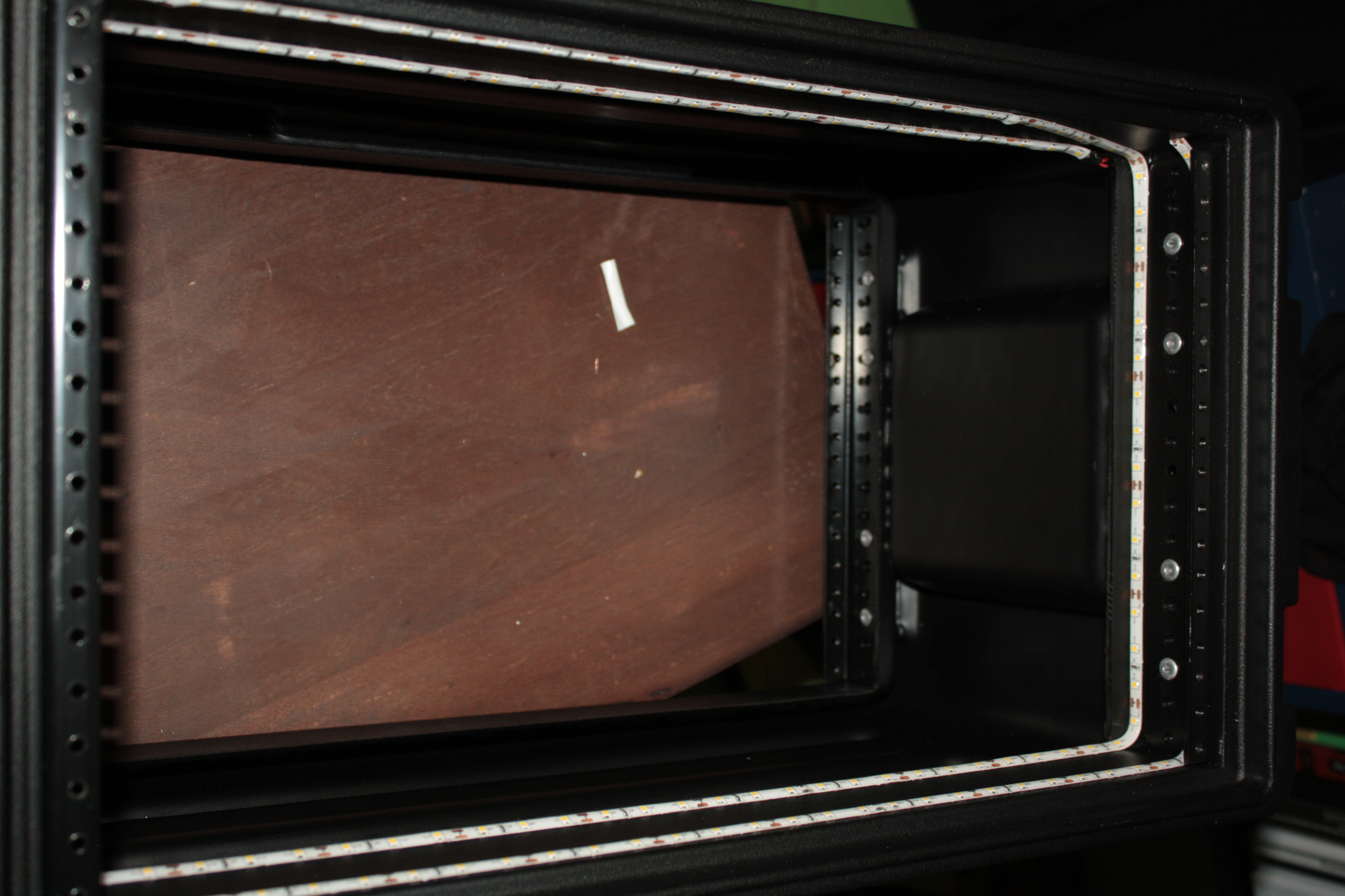
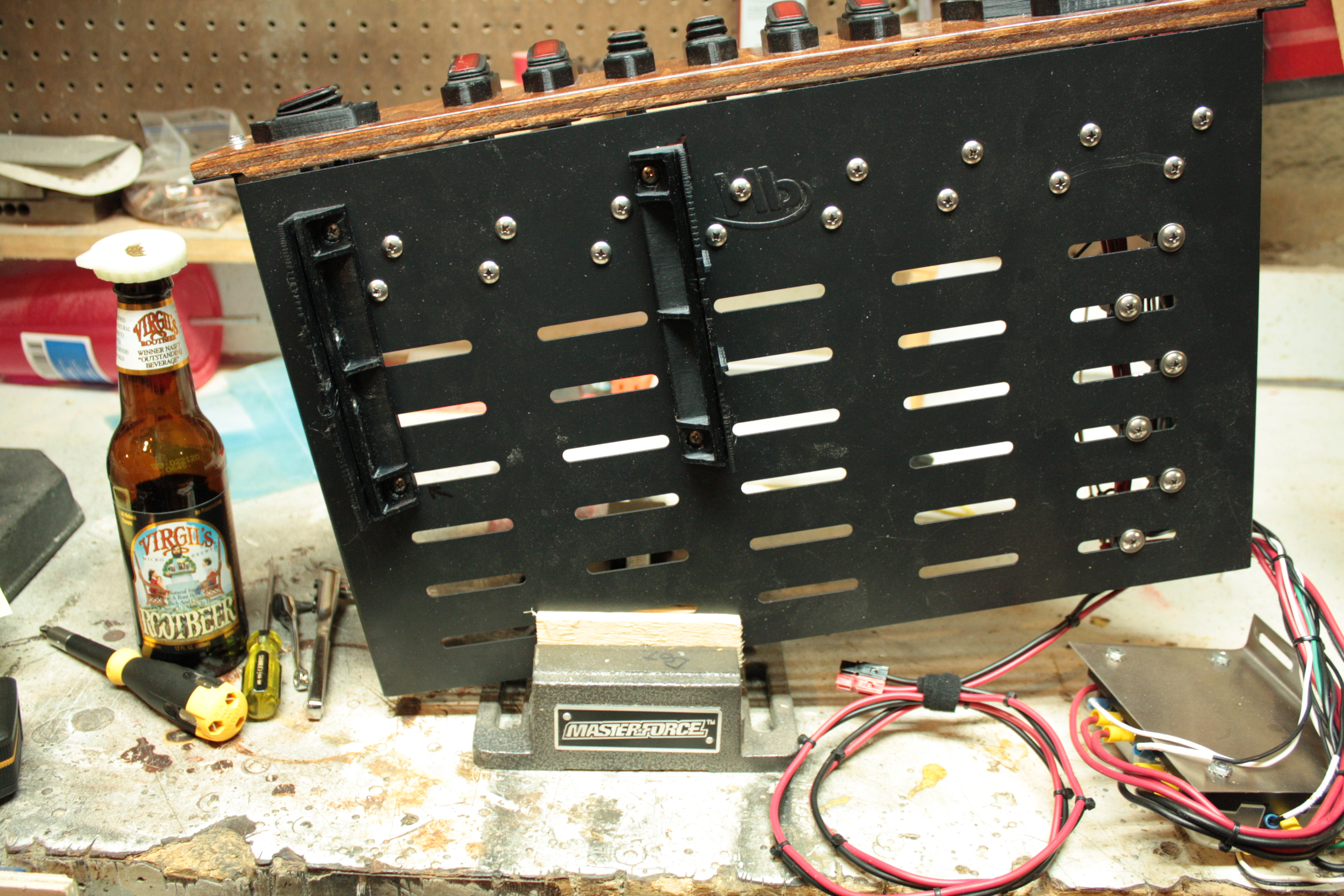
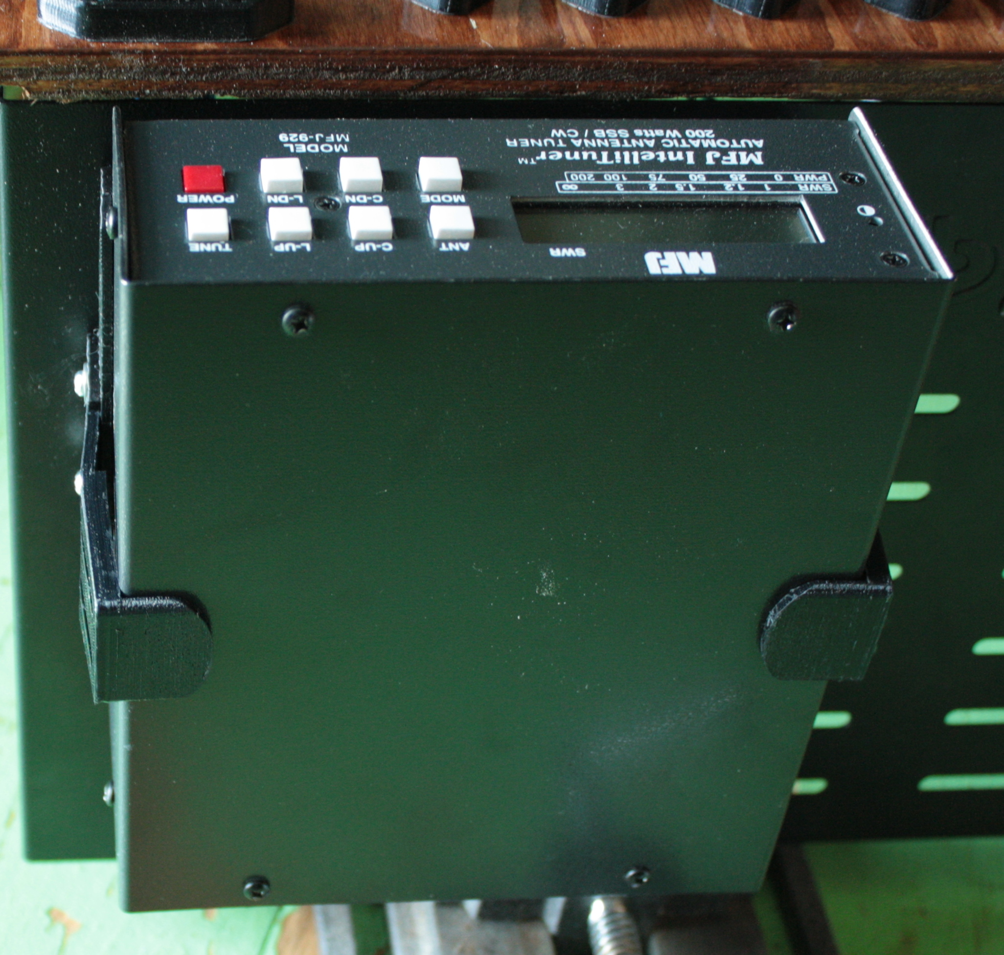
This picture was taken before I had completed the mounting horn for the match box.  Before I talk about the design exhaustively, let’s talk real quick about how well the antenna does as far as SWR is concerned.  Ironically enough, the only portion of the band that this doesn’t need a tuner is for 2 meters!  Below is a table of 4 SWR sweeps of the antenna.  I swept the entire spectrum with a single single with and without a counterpoise and a double slinky (two slinkys I soldered together) again with and without a counterpoise.  Generally a single slinky without a counterpoise is the winner, except for a few flukes.  Overall, for field deployment I’ll bring a single slinky and the counterpoise but not bother to put it on.  For 40m and up, this generally presents less then 7:1 SWR.  If 80m is my goal, I’ll put the double slinky on and go.

Unlike my last two projects with picture ad nauseum, I’ve picked a small subset for your viewing pleasure. 
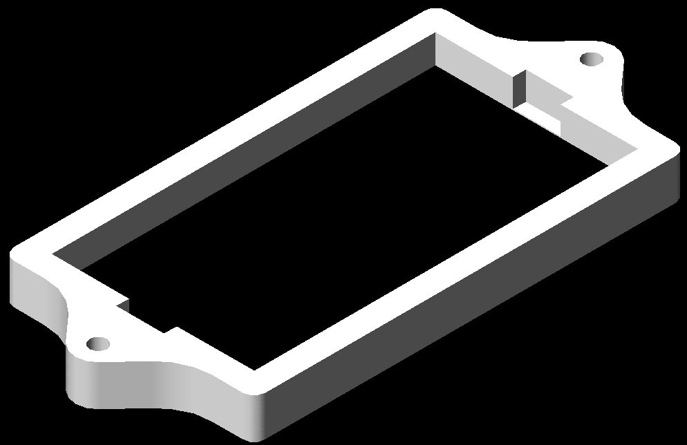
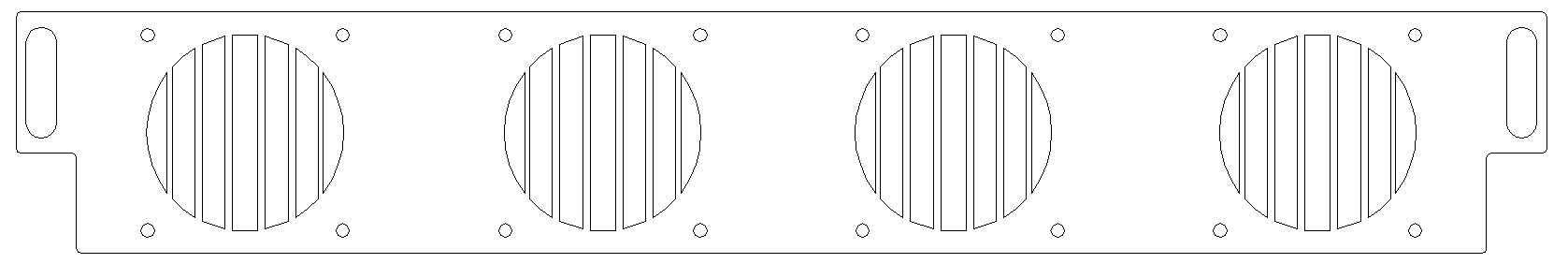
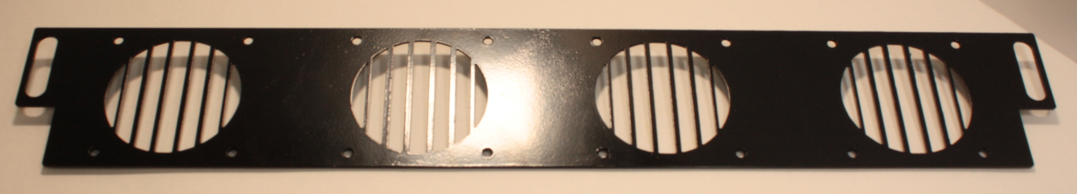
Here’s the CAD profile of the legs for the stand.  These were cut with a water jet from 14 gauge stainless steel.  The circles within the leg are to reduce the overall weight of the leg.  The notch at the base of the leg allows me to easily stake each of the feet.  Some would argue that its to heavy for the application, but the extra weight helps keep the antenna from tipping over without the stakes.  I think its a good balance.

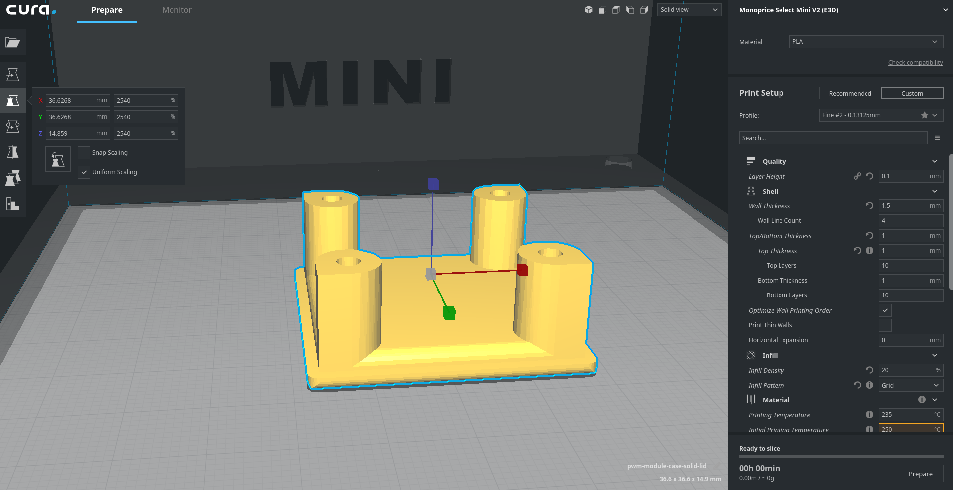
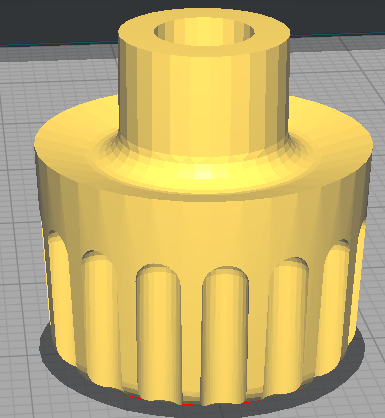
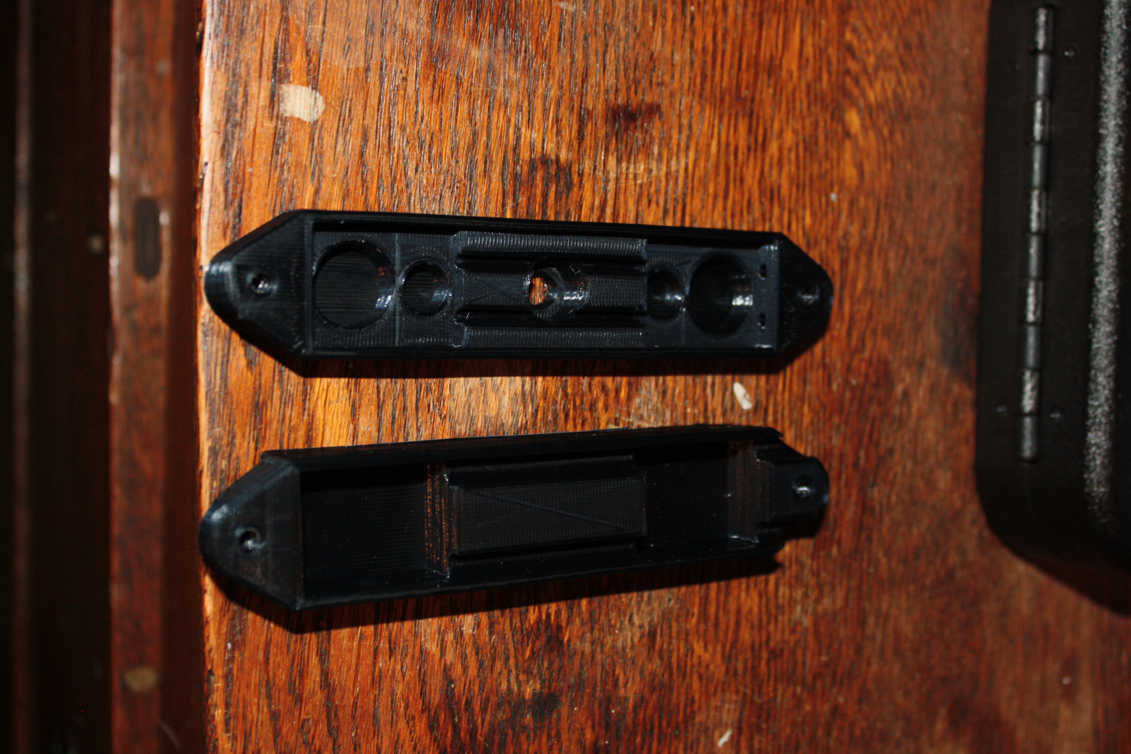
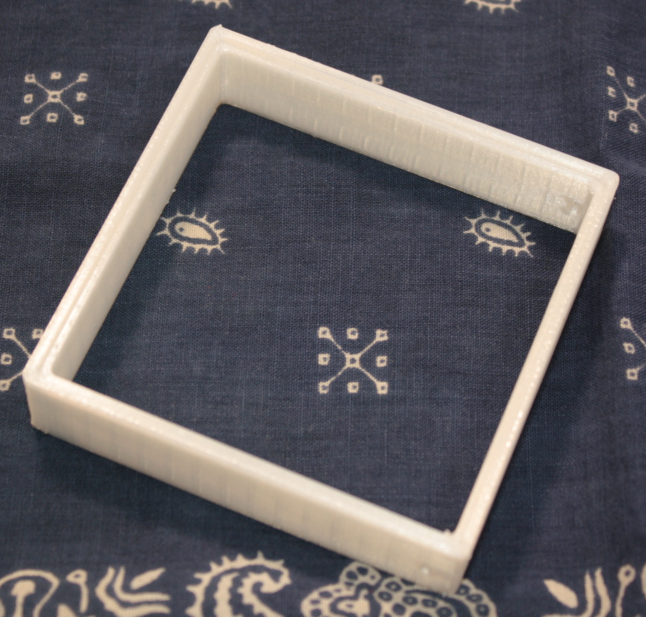
The clamps that hold the legs to the shore pole are 3d printed – as are many other things within my ham radio world.  There’s some 3m double stick tape to keep them in place.

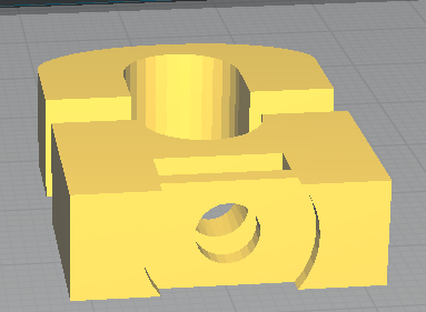
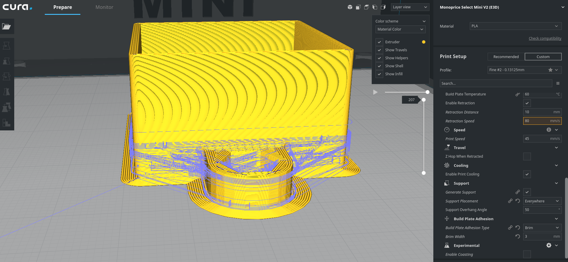
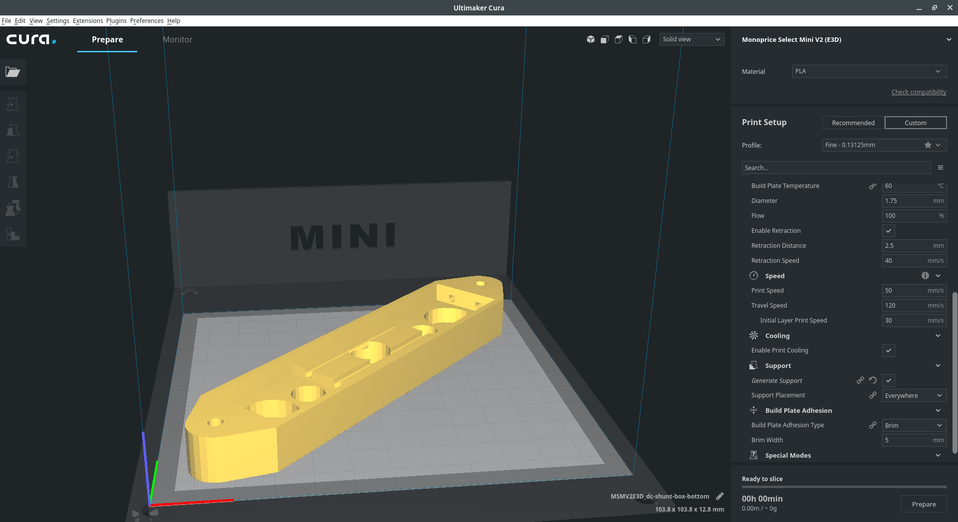
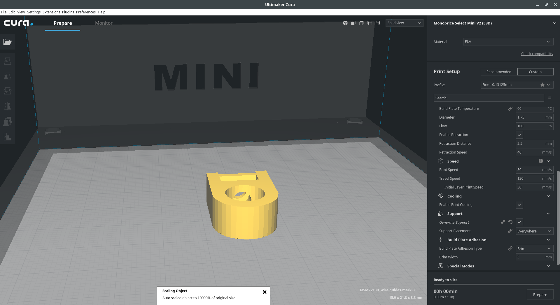
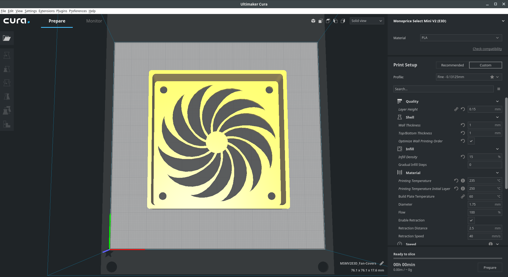
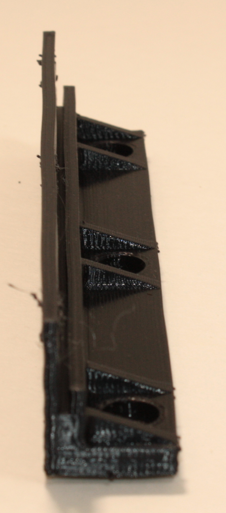
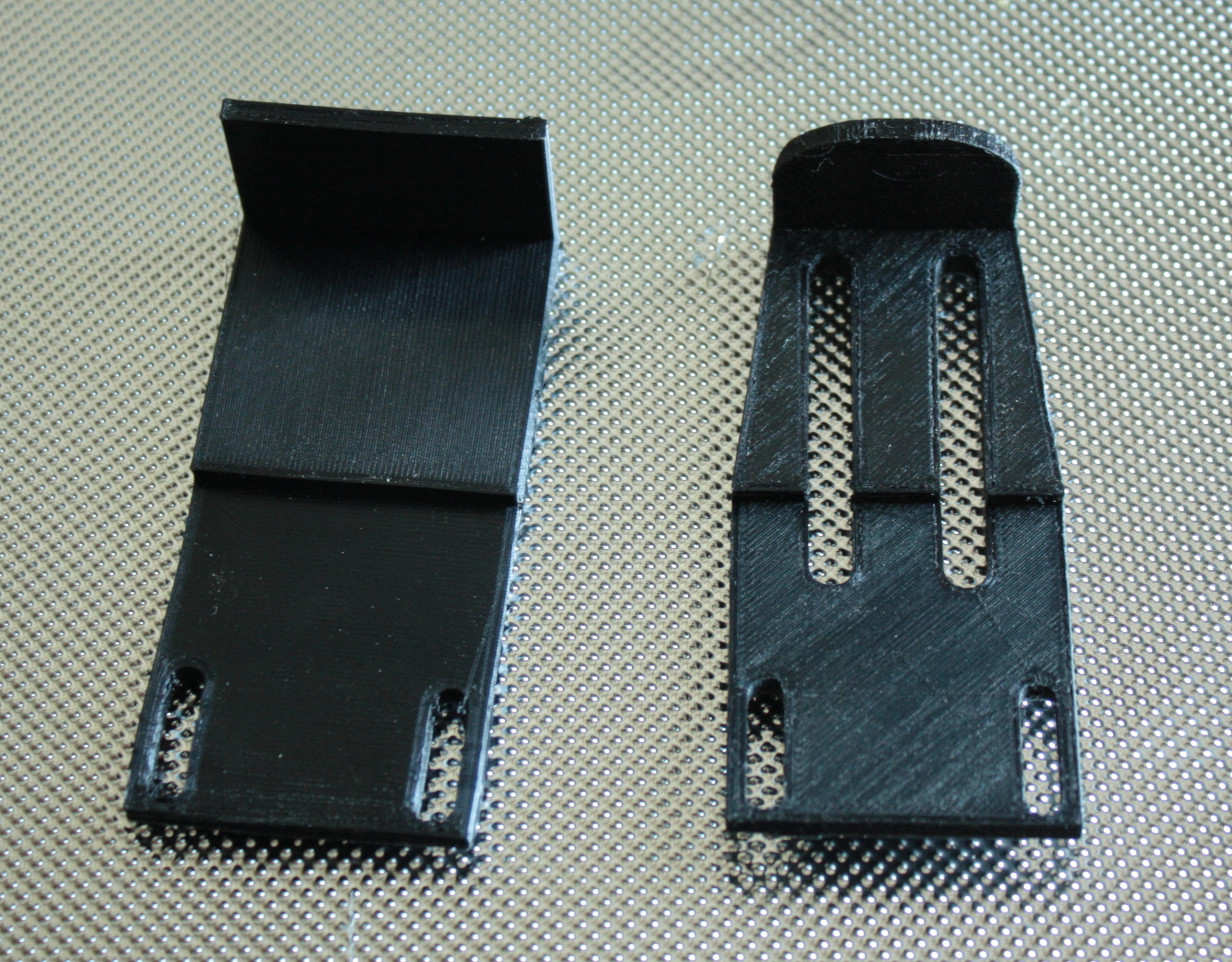
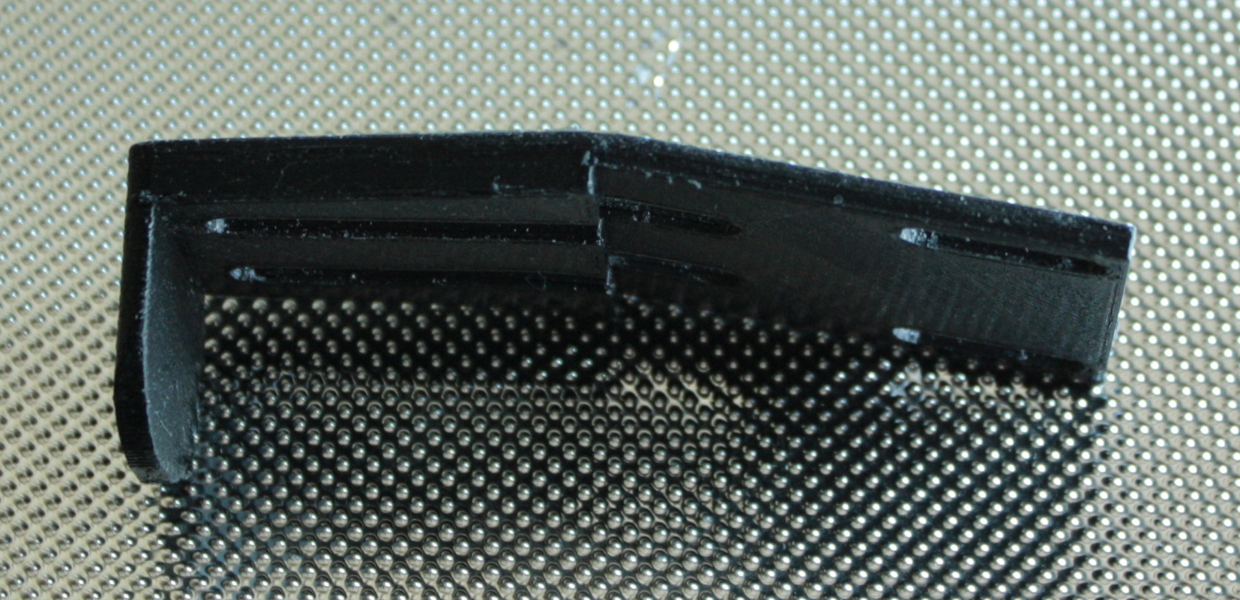
I designed the legs to pivot about the middle clamp so the top hole is drilled to provide clearance for the 8-32 bolt and lock nut that keep them in place.  The top and bottom clamp keep the legs in place.  For these clamps, the legs are tapped instead.  The leg flips to either the deployed position or stowed and an 8-32 bolt is threaded through.  This means that I don’t have to muck with a small fiddly nut in the field.Shot of the “clamps” being printed on my monoprice.   A few shots of the slinky.  One showing how the caps are attached to the slinky, and then a full profile of the single slinky and the double slinky.  I made small retaining straps using elastic and large buttons.  The wire coming out of the bottom is to connect the slinky to the match box.  I did the same sort of arrangement on both stacks of slinkies. Honestly, you don’t need to make it this complicated (in the video up top a simple lanyard clip is used but I always over complicated things. 
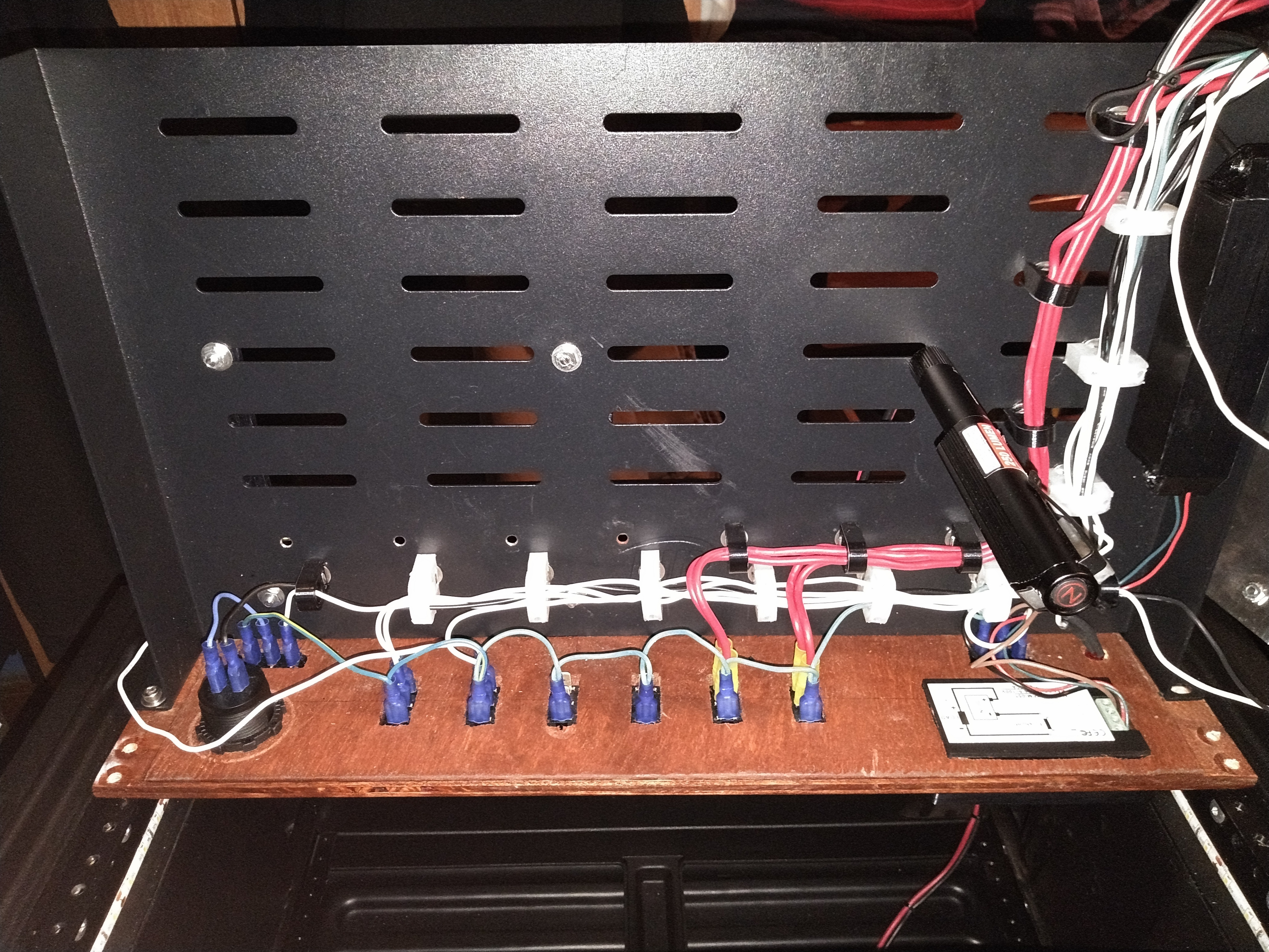
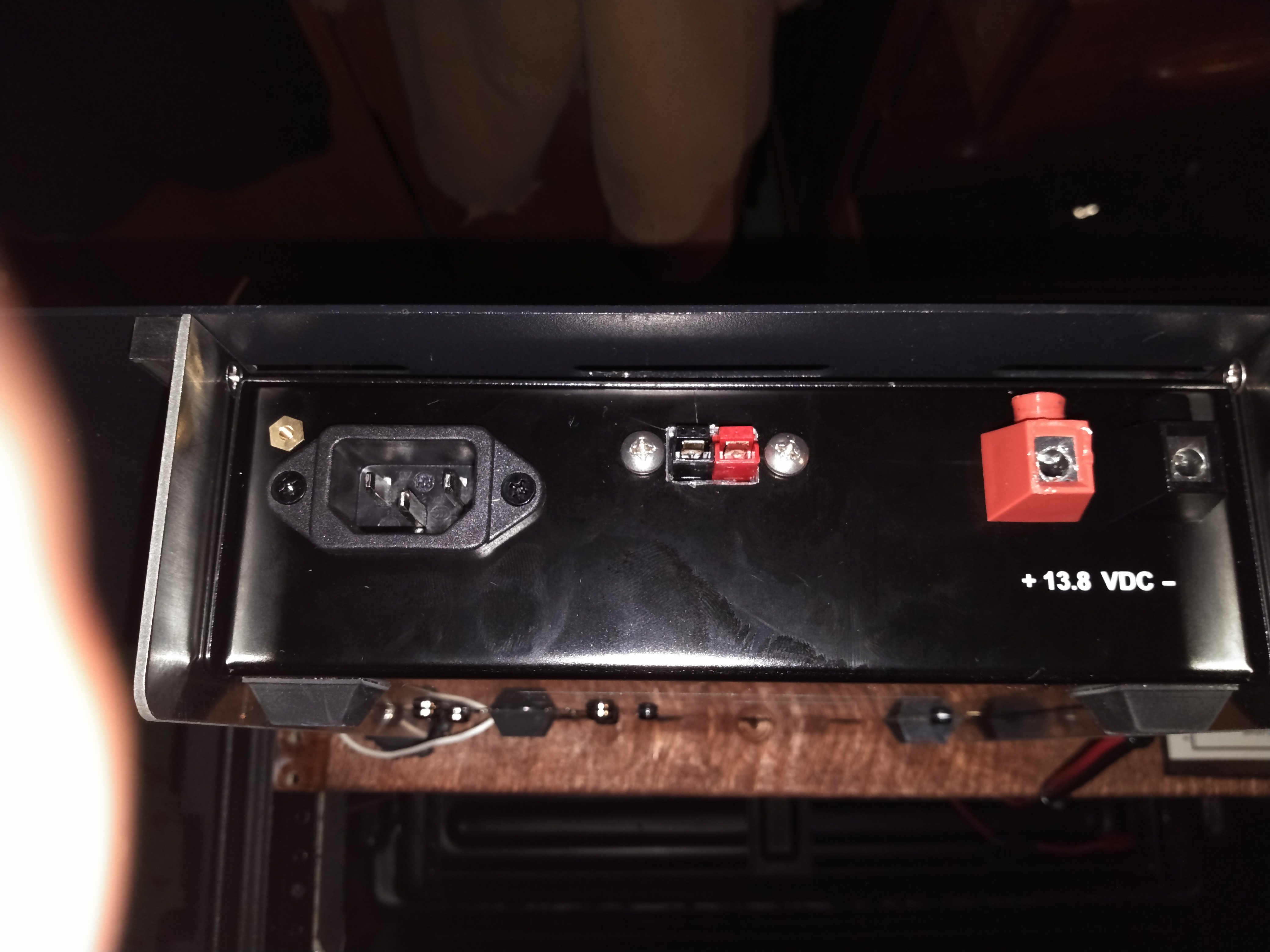
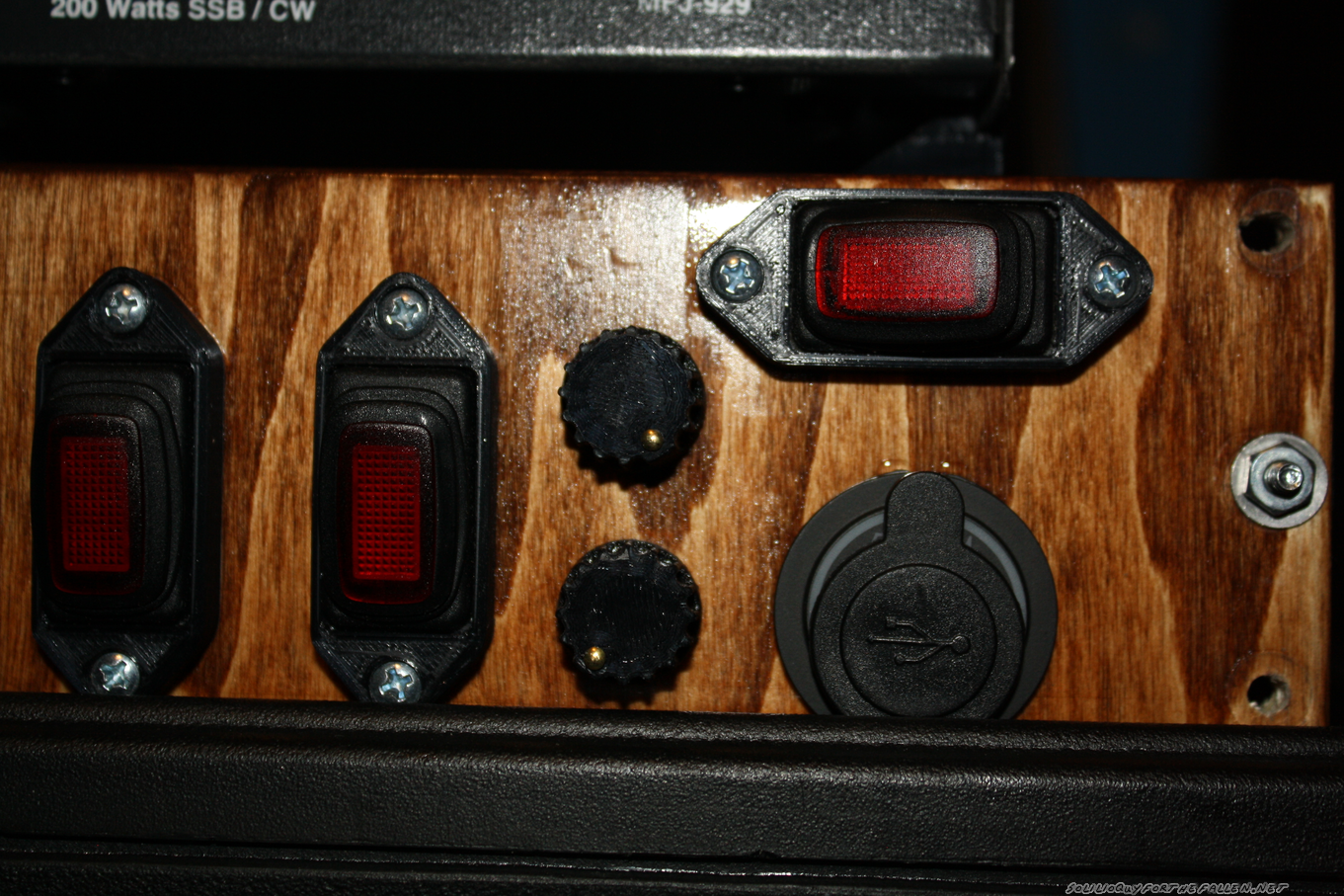
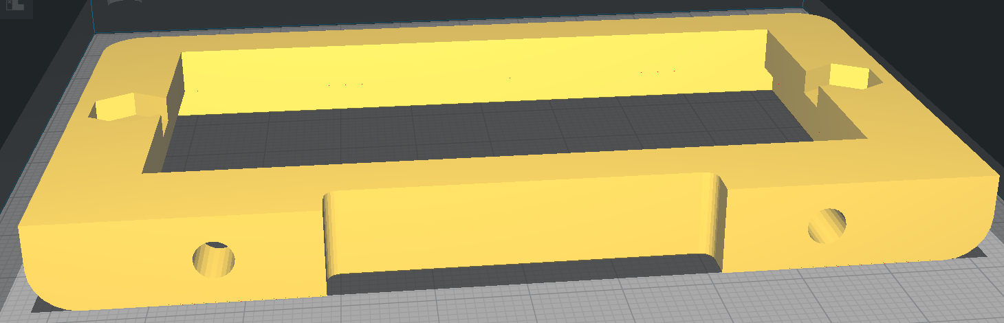
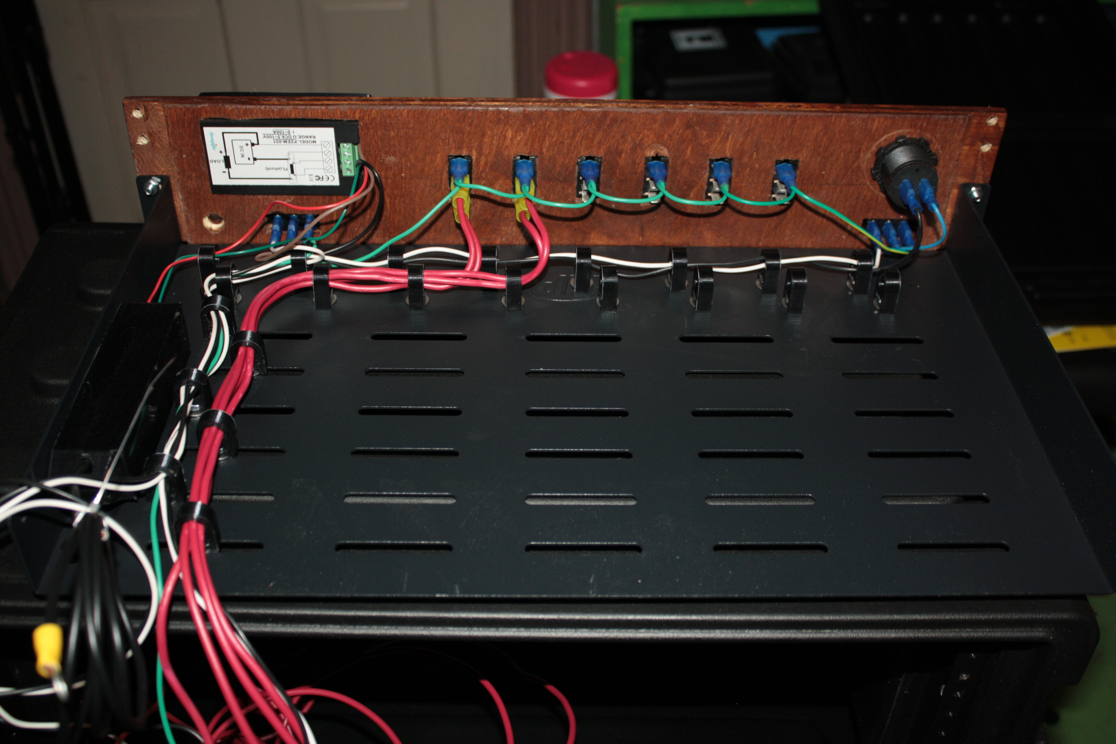
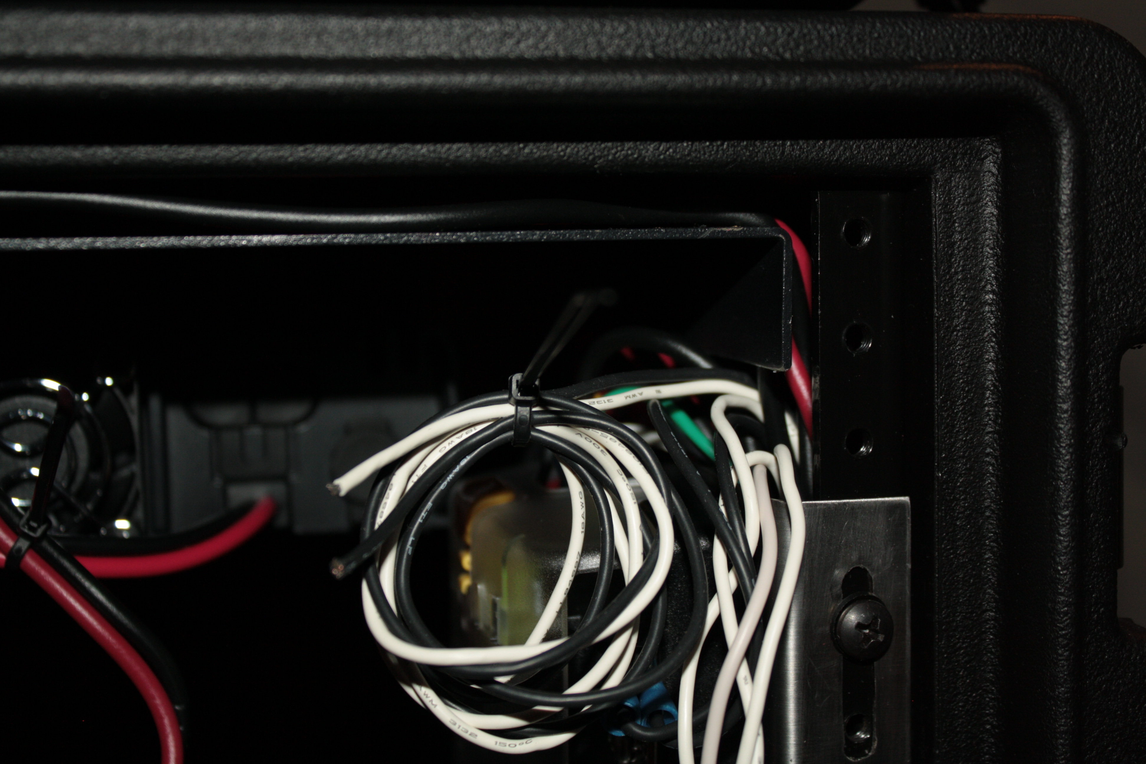
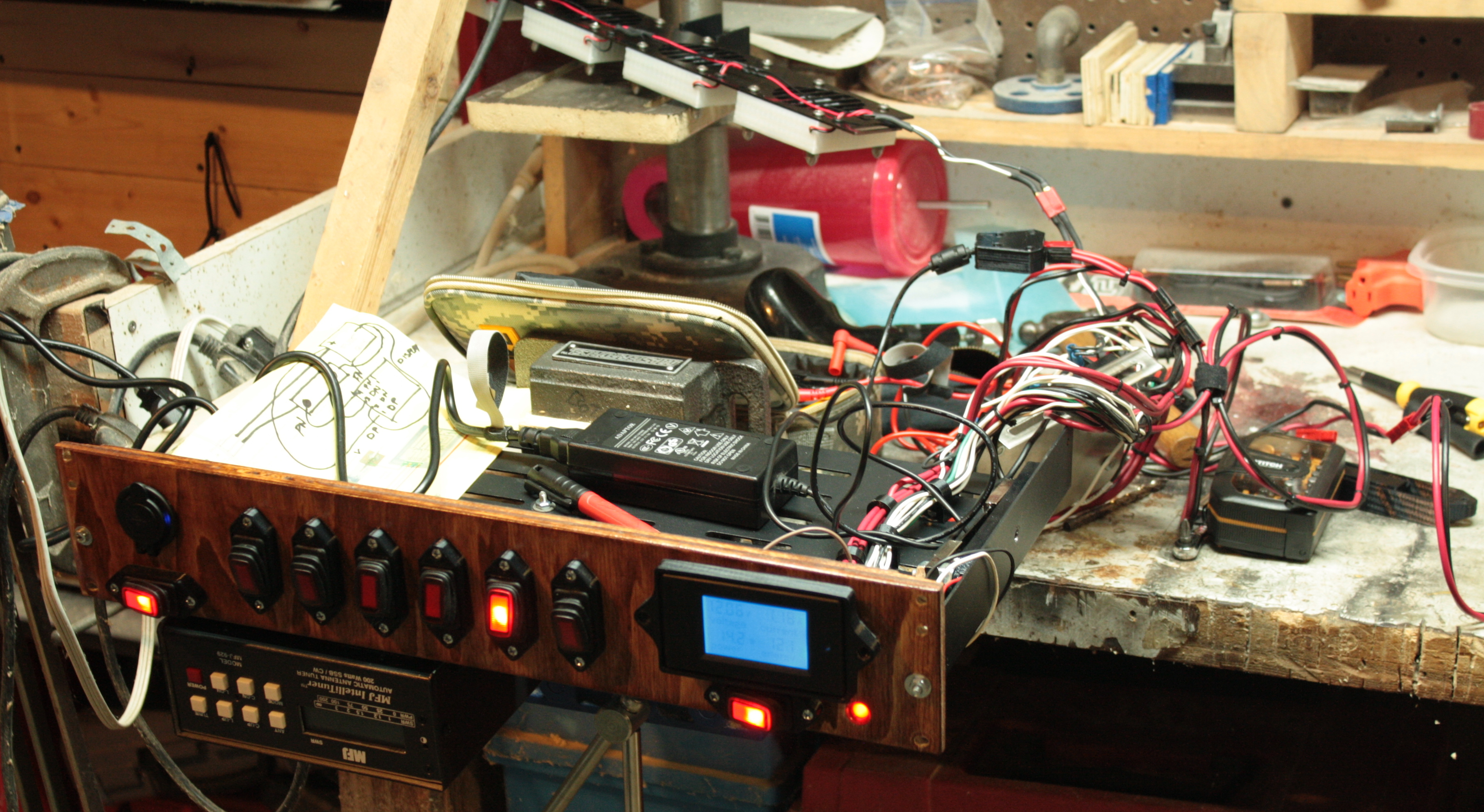
The matchbox.  The banana jacks ordered were to long and were almost touching each other.  I 3d printed some stand offs to try to clean this up.
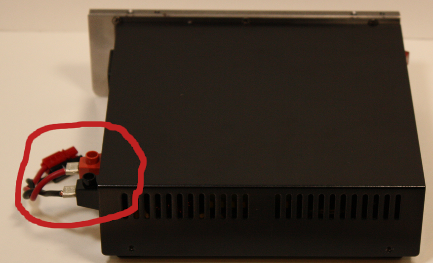
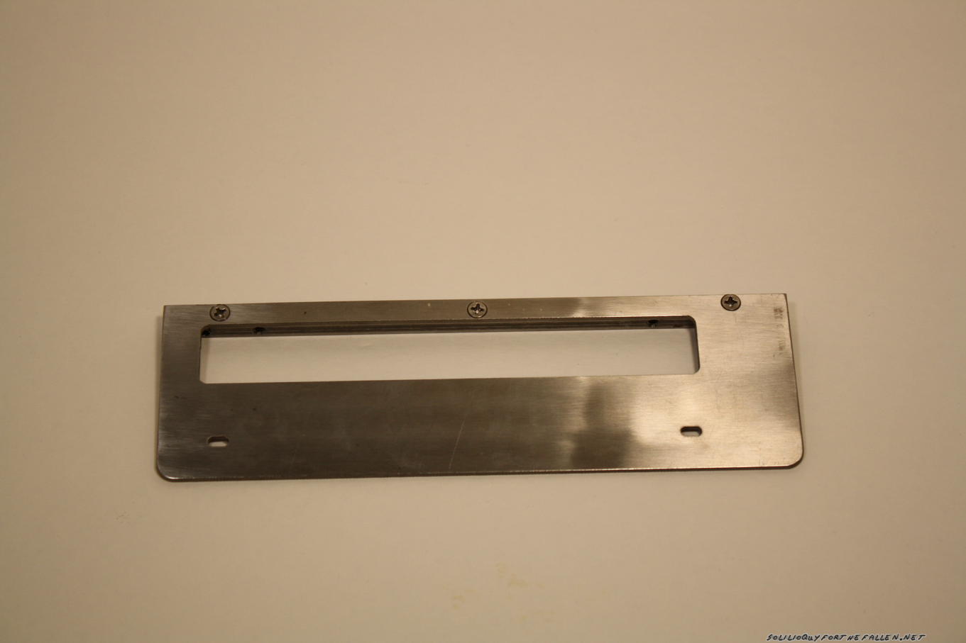
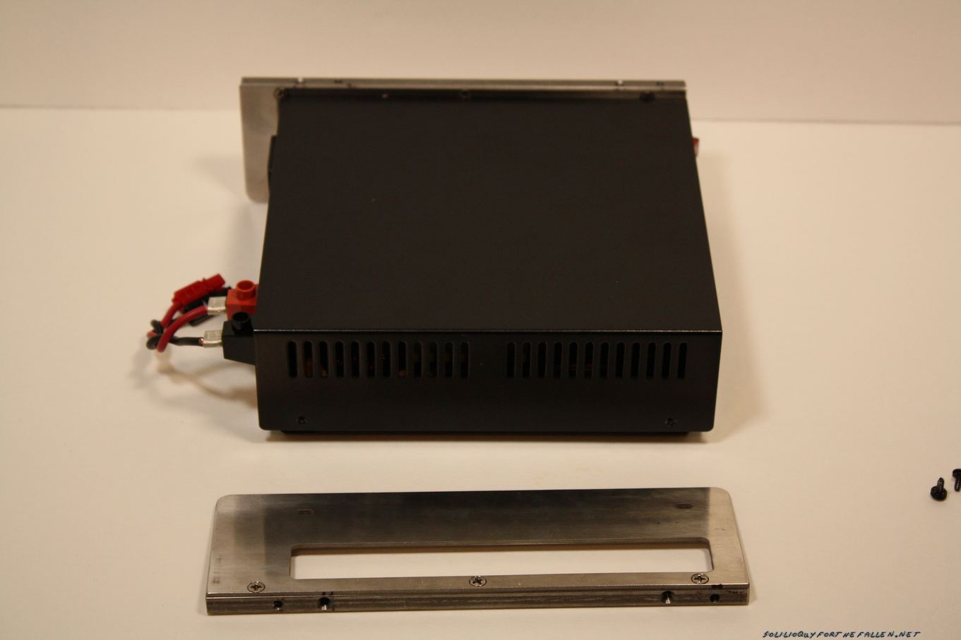
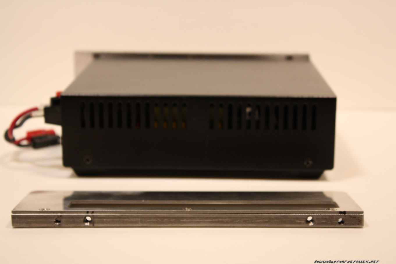
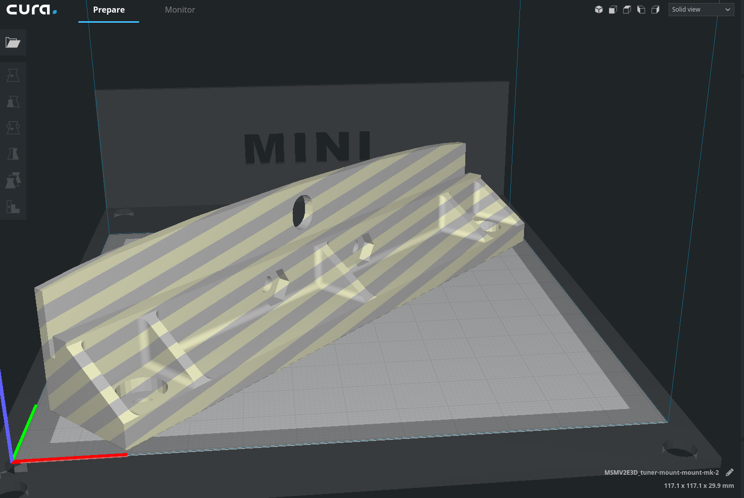
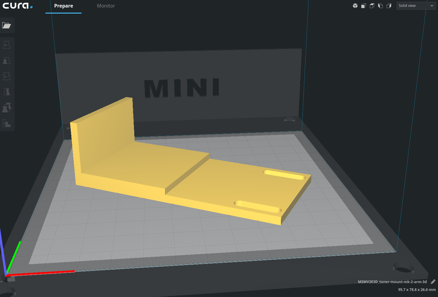
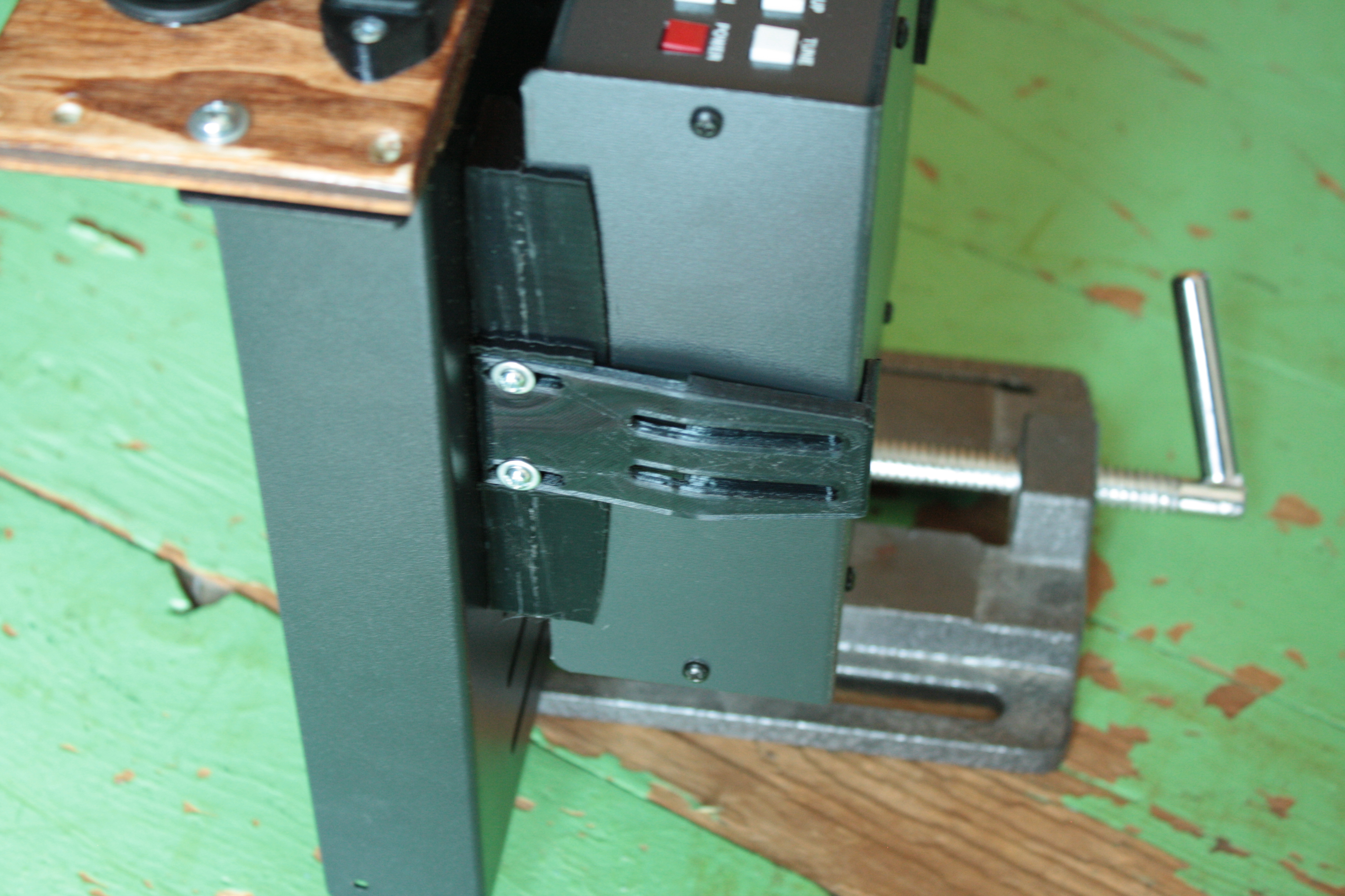
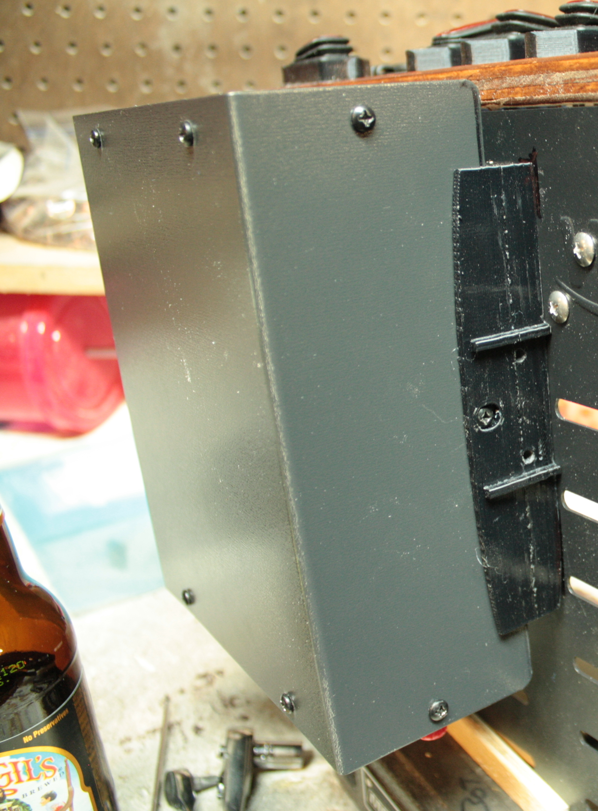
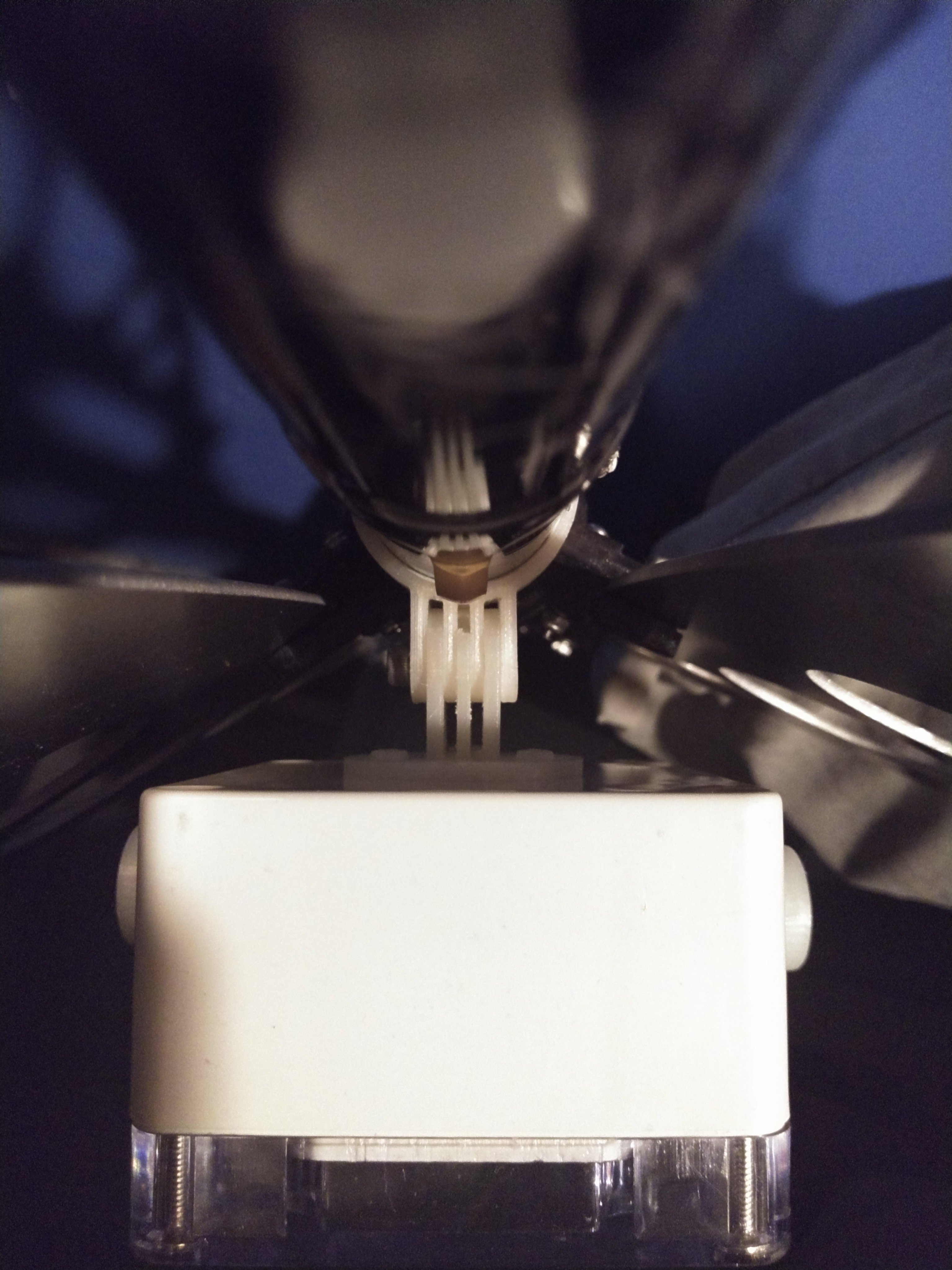
A shot of the mounting horn on the match box.
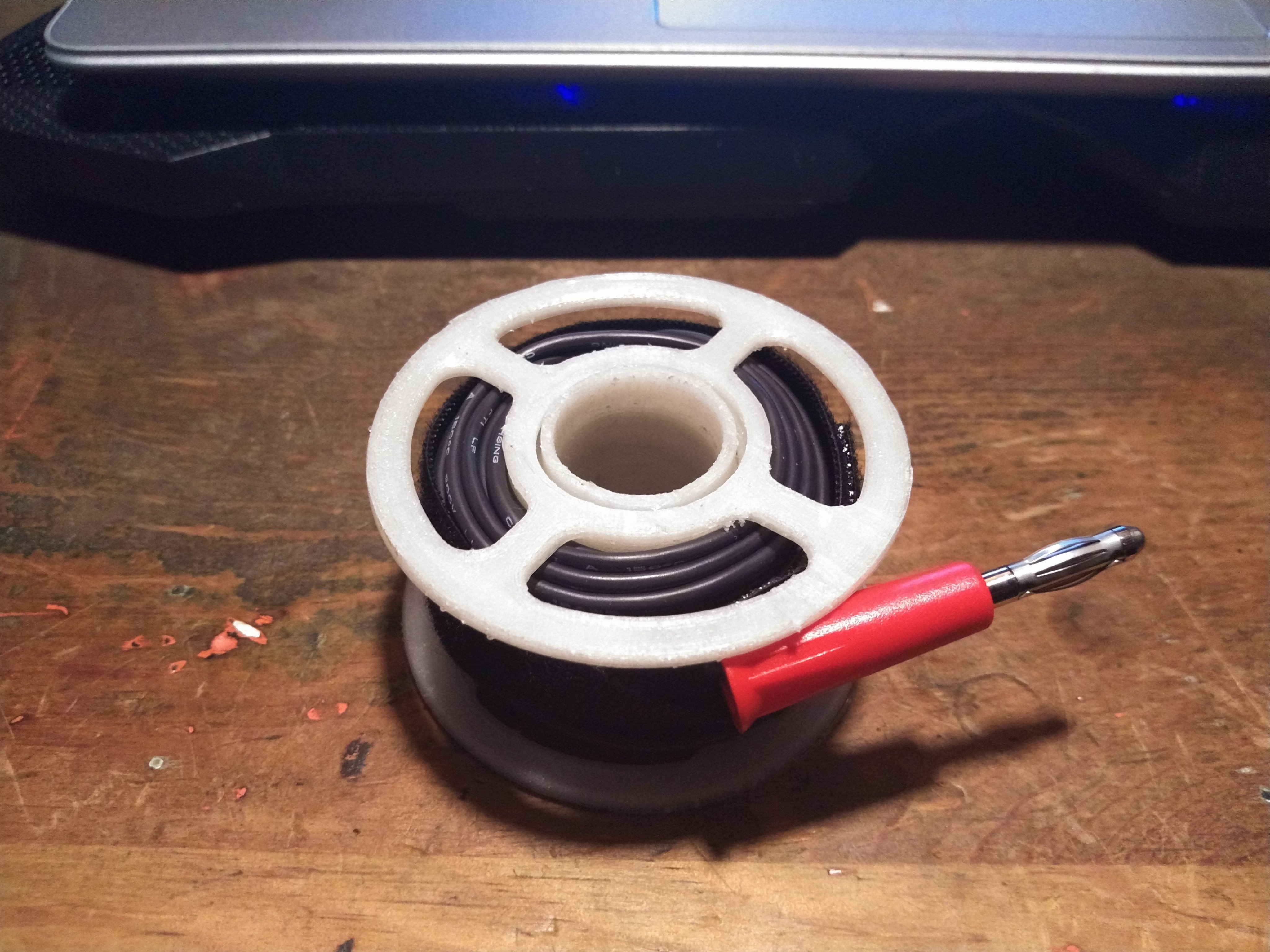
Found a neat spool on Thingiverse for the counterpoise wire (which per the above table isn’t generally needed).  Printed at 50% x & y, 75% z.


Shack-In-A-Box Mk2 Upgrades: Dimmable Lights, Fans, and Digital Comms

I came up with a few upgrades for my shack in a box:

  1. Integrate a set of Powerpoles into my Samlex power supply for a more aesthetically pleasing connection in the back.
  2. Add speed control/dimmer systems to the fans and lights so that I could control their intensity
  3. Mount my Signalink Digital Interface

These were all a result of working with the shack in a box over the last year. I was hoping to be done in time for the 2019 Field Day but with only one or two days on the weekends I wasn’t able to complete everything in time.  In my defense, the weatherman had predicted 2 days of thunderstorms straight, which is not quite agreeable to electrically charging long metal poles in the sky so I finished up my work on the shack in a box instead. The documentation below is roughly linear.

Build

Wire Guides, Redone

I knew the pwm modules I selected (more later) would require fitting a total of 10 new wires into the existing wire guides. The black ones designed in 2018 were filled to capacity, so I designed and printed some new ones. These were designed as two piece assemblies held together with #2-56 screws. By making the top removable, I saved myself recrimping all the spade connectors for the control panel as well as keeping having to keep the wires straight during reassembly.

Samlex SEC-1235 Anderson PowerPole Mod

Anderson Powerpoles are the defacto standard when it comes to amateur radio power connections.  My “main power feed” into my fused distribution box has powerpoles at the end.  This makes it easy to swap my “feed” between the on board Samlex SEC-1235 or off board batteries or other power sources.  Instead of the ugly “rat’s tail” I had rigged when I first mounted the power supply in November, I wanted to add integrated a set of powerpoles to the onboard Samlex SEC-1235 so it looked like it came that way from the factory.

Bah!

First, I opened up the samlex and pulled the guts out.  Since I would be cutting and filing, removing the internals completely was the easy way to make sure that nothing was fouled as a result. Hardened Power Systems offers the Anderson Autogrip. The idea is to press fit in the powerpoles and have a nice, clean presentation. I mounted them on the autogrip on the inside of the case to further clean the appearance.  The horizontal alignment was picked by finding a free space inside the case before I removed the circuit board and marking it with a sharpie.

After getting the powerpoles into the autogrips and then I reassembled everything and put it back in my mounting rack.  Originally, I intended for the samlex to tuck fully inside and under the bottom shelf.  However, I had some empty wire guides that stopped the samlex from being able to mount that deeply.  While I was swapping to the larger, two piece design I removed the additional wire guides I wasn’t using from the shelf.  This gave me the extra depth I needed to fit the samlex under the shelf, as deeply as I would have liked to originally.

Mounting the PWM Modules

The primary reason for pulling the shack in a box apart this year was to add a way to control the speed of the fans and the brightness of the lights.  I bought some bare PWM Modules from Amazon, knowing I could design and 3d print cases. The legs on the top hold the module down inside of the case.

The cases were designed to also mount the PWM modules to the bottom shelf with a pressed in 8-32 nut. I thought that I would need to hold the lids on with 4-40 screws and included the holes and nut mounts but later decided that the fit was tight enough that the 4-40’s were not needed.

Here is the cura rendering of the box and then lid.

Mounting these was a relatively simple affair, as was connecting the wiring.

Then I needed to mount the rheostats on the control panel for access. I placed some masking tape on the control panel, then put double sided tape on the knobs. I then test fit where the knobs looked the best, and I ended up centering them between the last switch and the USB outlets. I drilled two small 5/32 holes to mark where the knobs would be.

The 3/8″ plywood I used for the switch panel was actually as thick as the overall length of the thread and shaft for the rheostats.  To make it work, I drilled out the front side with a 1/2″ forstner bit.  I need to make some new knobs that would “hide” the deep 1/2″ hole I’d drilled.  A nice, chunky, friendly knob was designed. A small hole was added so that I could press in a small brass brad nail to indicate the position.  The size of the knob hides the 1/2″ hole I drilled, and has a shoulder that presses neatly onto the rheostat’s shaft.

Mounting the Signalink Mount

The last question was how to mount my signalink. I considered mounting it quite a few different ways but decided that I didn’t want to modify the case of the signalink in any way. So I elected to mount it from the face.

Mounting was tricky, but doable. I had to drill two new holes for the faceplate into the shelf. Then, I pushed the 8-32 screws I wanted to use into the bottom holes. The the screws and faceplate were then bolted onto the shelf. I removed the faceplate (and board) from the signalink. Then I pushed the case in from the back. I slid the faceplate and board back in. I printed this with pretty tight tolerances, so I had to push everything in square from all sides. I reattached the faceplate to the case, then used a set of 8-32 screws with washers to make sure that the signalink couldn’t push back on the front.  The faceplate sits on a small shoulder on the mount.

And here’s a demo of the lights and the fans.  I’ll demonstrate the Signalink in a later post.

Note: As before, I have chosen to provide many of the solid model STLs for the 3D Printed Parts I used. However, I provide these STLs without support. I may have suggestions or warnings but they are provided as is. I hope that they are useful to you, but they may not be. Free is free.

Parts

3d Printed

Ordered Parts


Pistol Crossbow Antenna Launcher

Sometime around June 2017, I built an end fed antenna with match box. End feds are not … great antennas but they are decent for the space they take up in a go kit. The way mine is currently configured works well down to 40M. End feds are basically a long length of wire, with a 9:1 UNUN to help your tuner match it to multiple amatuer radio bands.

The real question though, is how to get the blasted thing up in a tree. Generally, the higher you can get an antenna, the better off you will be (unless you’re trying to do NVIS, but that’s a whole other subject). I considered using a modified spud gun, but I haven’t had good luck with spudguns in the past. I also didn’t like the idea of having to either hand pump the cannon or bring an air compressor. The NPOTA I attended we did not have an easy solution for powering a compressor either. So, here’s the solution I came up with.


Originally, I had been planning on mounting a fishing reel onto a slingshot and launching a lead weight with the slingshot.  However, I was at a local farm supply store and saw a Bolt Crossbow.  I thought it was a much better solution (and more accurate) then a slingshot and smaller then a bow & arrow, so I bought it.  I had gotten the zebco 202 on clearance at walmart that I was planning on mounting to a slingshot for getting ropes high in trees.  Since this crossbow can handle both purposes, I decided to use it for that.

Then, I had some layout and decisions to make.  I wanted to have two bolts on board the crossbow, and then the fishing reel.  With that information, I laid out how large a piece of 1×4 I needed.  I cut a channel with the table saw for the crossbow to fit in down the middle of the block, then drilled two holes in the block.  Then I drilled and tapped the crossbow to mount the block.  I drilled two holes to mount the fishing reel, then drilled and tapped the reel so I could mount the reel to the block.  Finally,  I drilled two holes on the opposite side of the reel for the bolts to fit in.  A hair tie (stolen from a sister) retains them.

All in all, a pretty simple build.  I keep toying with building another version, able to be taken down making it smaller and more compact, based on an ar15 pattern rifle.

Parts List:

Additional Resources


Shack-In-A-Box: Onboard Power

In a previous post, I documented the build process of my ham shack in a box.  Notably lacking was a power source to power the box, and this was something I decide that I would add and document in a later post.  Initially I though I would pull the server supply out of this box and mount it to finish out the calendar year, then purchase a solution like the Samlex closer to next year’s Field Day.  However, I decided instead of coming up with ways to mount two separate power supplies I would save myself the time and trouble and acquire the samlex supply this year.  There were issues with noise on the 80M band and I’m pretty sure the power supply was at fault.

After searching the current market offerings, I selected the Samlex Desktop Switching Power SEC-1235.

This power supply was selected because it was relatively featureless, and could provide 30 amps continuous, and 35A Peak.  With the onboard power monitoring and the way I intended to mount the supply, there was no need for the SEC-1235M model, which has its own onboard voltage and amperage display.

Samlex sells a mounting rack that allows you to mount a radio together with the power supply and I co-opted this idea for my mount. First, panels were drawn and a shop favor invoked for them to be cut on the water jet.  Then, I purchased keystock to mount the panels to, and to mount the power unit to the shack in a box.

Keystock drilled and tapped, panel holes cut & drilled

Keystock mounted. Need flat head screws for flush mounting.

Removing the factory screws and using original holes to mount the panels.

Another view of mounting the panels

Final Mounting

Another View

Fitted into the shack in a box


Shack-In-A-Box: Initial Build

What’s the point?

Go boxes exist across for a spectrum of purposes. Perhaps you have a sewing box, or a toolbox, or a box with everything required for D&D. By doing this, you have everything needed for that particular task and can be ready to go within a few moments notice – or not have to get everything collected for Friday’s game and you’re already late. Building a ham radio go box is no different – you can grab the unit, head out the door and and once on site have everything you need to operate.

I am primarily a portable operator (as a result of my HOA) who must set up each and every time. With a go box, having all my radios are mounted in a single portable box with the radio gear and power connections set up means I will have much longer to operate – and that much more isn’t left to chance.

I was inspired to build my go-box after joining the Ham Radio Go Box group on facebook. I ended up throwing my new 2m mobile in there as well as a result of starting to run my club’s monday night net. Here are pictures and remarks of the process.

What’s in the Box

Check out the for pictures. In the go-box, I have

  • HF + 2M/440 by the Yaesu 857d
  • MFJ 929 HF tuner connected to the Yaesu
  • 2m/440 + Crossbanding from the Alinco DR-735t
  • Built in illumination for dusk or after operations
  • Built in cooling for both radios
  • Onboard 120V power conversion and a power monitoring system for amp load and voltage (voltage is monitored on battery power)
  • USB Phone charging

Build Log

I drew an initial layout in cad to determine if I should purchase a 4u or 6u rackmount case. The rackmount system comes from the portable audio world and specifies a certain amount of space and a mounting system. Trying different variations, it was decided that a 6u box would provide for all the equipment I had currently, and some future expansion. I decided that purchasing a commercial rackmount would give me better results then building my own box as I have seen some do.

Ultimately, I selected the SKB 6U Roto Shallow Rack unit over a comparable Gator Box (or eurolite) for two reasons. The first was that the SKB features an internal gasket that while it won’t make the water proof, will certainly help keep out the spirit dampening rain storm. The second was that the SKB was better reviewed then any other rack mounts I had found. The additional sturdiness of the unit was worth the additional expense. I avoided the particle board solutions by Eurolite & Musician’s Friend due to the weight. Both the wood and plastic boxes are flight rated so there should be negligible difference in their durability with the weight of the poly boxes being at least half the weight of their wood equivalent. Radios & other things will make the box heavy enough on their own. Then, I needed to go from the vertical pillars of the rackmount system to a horizontal surface to mount the radios, tuner, and other gear. To rack them into the go-box, I ordered 1u racks from Navepoint. By ordering directly from Navepoint I saved about $2 each rack, exchanged an email for another $5 off, and still had free shipping. Much cheaper then purchasing from Amazon


I used the mounting brackets provided by yaesu and alinco for their radios. No reason to reinvent the wheel for a custom solution when what was provided works well. The radios were mounted in the slots in the navepoint shelves with the brackets that came with the radios from their manufacturers. You’ll note that at times the radio shelf is clamped a small masterforce vise. This method of keeping the shelf vertical to work on it works fairly well, especially when you let gravity work to your advantage. This is my go to method for handling the shelf when it is outside of the box.


A Blue Sea Systems 6 Circuit With Coverwas sourced from amazon. This helps protect the radios from short circuits with fusing, as well as providing a neat and clean way of distrubuting the power from whatever source I am using. I should note that its built with metric standards. Because of this, i found it a bit difficult to work with as I have minimal metric tooling. An initial fitting was done to make sure I was on course with the space requirements of everything so far. (I apologize for the potato phone pictures.)


Because of my desire to run the system from a battery, I ordered DC Shunt Monitoring System from amazon. I chose this particular model as opposed to the some of the meters around for its low draw – and that I can shut of the monitor and have no draw at all. The system displays the current voltage of power system, amps in use, watts, and watt hours. I needed a way to encapsulate the shunt, so I designed and 3d printed a shunt box that would allow me to mount the shunt in any orientation. The bottom of the shunt box has two hex hole for a 6-32 nuts to press in. The top has holes for 6-32 fasteners to fit through and tighten via the 6-32 nuts. The center hole is to bolt the shunt mount on the frame with a 1/4-20 bolt. STL below. There are tunnels for the main power wires and the display relay wires.


To mount the monitoring display, the power switches, and a USB charging port, I needed a small panel about the size of a 2u panel (3 1/2″ x 19″). The layout of the switches, power display, USB Charger, and control switches was mostly laid out on the fly. After layout, cutting, and test fits the board was sanded through to 400 grit and stained. Rustoleum Spray Lacquer was used as a protective coating. I found that laying the piece out horizontally and using heavy coats resulted in the best surface finish.

Each function of the box (such as the radios, the usb charging ports, the monitoring display) can be switched on individually. I sourced a number of 13.8 VDC 25A switches from Digikey instead of using lower amperage switches and relays – again with battery powered operation in mind. Because the switches were designed to be mounted in thin plastic, not plywood, I needed a way to engage the locking tabs on the switches on the board. Switch mounts were designed and 3d printed to engage the locking tabs on the switches and screw into the face of the board. The monitoring display was also made to be mounted in thin plastic or steel, so a frame for that was also designed and 3d-printed.


To keep the wiring neat and tidy as I run it to the switches, power supply, and more small wire mounts were designed and printed with my monoprice. An 8-32 nut is pressed into the slot, a #10 fender washer is placed in the top, and then it is bolted onto the tray with a 8-32 x 7/16″ machine screw for wires to run through. This helps keep the wiring tidy and supported.


Adding a feature I probably don’t need, stick-on LED tape was installed around front of the box. First the surface is prepped with isopropyl alcohol and then allowed to dry. The LED tape is applied, leaving the power leads in a supposedly convenient position. Deans Connectors were ordered to allow me to connect the switching panel to the LED tape. With these connectors installed, it becomes trivial to disconnect the lights from the switch board. High quality adhesive shrink tube was applied over the solder joints to protect against shorts.

After this, I began the final fit up and cable management of the wiring inside the case. This was fussy, test, trim, retest, retrim, crimp, retrim, install, remove work that consumed the better part of four days of work. Cable management is an important part of any job and I didn’t want wires hanging in loose bundles looking like garbage – hence printing and installing the wire mounts. Here you can just see the power feeds for the radio fitted over the top of the shelf. They are then fed down through the slots in the trays to each radio. Later, I realized that I needed to open up the slots as an powerpole can’t be pulled back through. Two of the ventilation slots were cut to form a generous slot to pass the powerpoles through. These were cut with a dremel, and then some hand filing to clean up the holes. I also needed to remove a section of the top rack on the side so that wires could pass out from behind the distribution box and make the required connections. Again, this was cut with a dremel and then hand filed.


I had to decide how to hook up the radios – whether I was going to use the factory connectors or powerpoles. I ended up with a mix of the two. I removed the alinco connector and switch the radio directly to Anderson Powerpoles. For my 857, I decided to keep the yaesu connector because of the brown wire (a stupid item imho but best to leave it). Powerpoles were installed on the drops, then a generous coating of dielectric grease was applied. I’ve read that powerpoles corrode quickly so this will help keep them from oxidizing without damaging the ability of power to flow across the tabs.


Axial fans were ordered to provide additional cooling to the radios. The fans from digikey were selected to to provide maximum airflow with a low 38.5dBA noise. If needed, I can mount a rheostat to slow the fans and lower the noise, at the cost of airflow. A fan mount was drawn in cad, and a shop favor called in for the panel to be cut with a water jet. Once it came back from the shop, a coat of rustoleum professional grade primer and then rustoleum gloss black was applied. I refuse to utilize krylon paints in my shop. I broke a fan blade just by tapping with with my finger, so I clearly needed to provide some protection to the fan blades. A fan cover mirroring the style of the grid on the fan mount was designed and printed. I reasoned that the fans could push no more air then they could pull, and mirrored the design of the fan mount. To save print time in the future, I redesigned the guards to have a sleeve and cover. While the sleeve adds slight complexity to the walls and increases their print time, it will save roughly 3 hours should I need to redesign or reprint from breakage the guard grid in the future. Here are the sleeves, and the first & second iteration of the guard. Printing with just shoulders pressing against the fan saves an hour of print time on the monoprice.

Small rubber grommets were ordered and 3/32 holes appropriate for the grommets were drilled. Grommets installed, the wires were passed through the side of the guard, and then wired in parallel to a deans connecter which was then hooked to the appropriate circuit. As will the led lighting, this makes it easier to service various parts of the box. The fans are attached with 6-32 bolts and acorn nuts for a finished look. The fans pull air from the rear of the case and push it towards the front. The user of the go-box experiences a slight breeze.


A “rack” of sorts was designed and printed for the MFJ-929 HF Tuner paired with my Yaesu 857d. This rack barely fit on my monoprice – I had to set the bed size to 121mm x 121mm and get rid of the brim to print these. Taking advantage of rapid iteration through 3d printing, here is the mark 2 version of the tuner mount mount, which loses a mounting hole on the base, and eliminated the need to drill and tap the side of my tuner as I had originally planned. A slot that fits to the center screw on the side of the tuner helps center & retain the tuner in these mounts. Then, a sliding armature was designed that will insure the vertical retention of the tuner.

With the initially printed arms, I had issues with the print warping, and the arms tilting back. I lost some faith in the retention ability of the arms because of this. I initially planned on printing the arms in a way that they couldn’t warp from heat differences as the layers were applied. I changed from the initial arm design to Mk 2.5 to help reduce the print time, and to make things look nicer. After a test print with the arm at about 15° on the print bed I decided I didn’t like the results when I cleaned up the print. So instead, I printed two more arms, gently heated the pla prints, then pressed down with a wood slat to intentionally warp the print so that when bolted onto the mounts, they would squeeze down and against the print. Mk 1 & Mk 2 below.

The fan panel makes it harder to get to the pl-259 jacks on the back of the radios. To make it easier, I ordered and installed some right angle adapters to the radios. The 857 was connected to the tuner with a cable that has a right angle connector.


Closing Thoughts

At this point, I’m posting the build log. I will have to make a few updates for things such as integral power supply, hand mic mounts, and the smaller 2M antenna I’m building to keep in the go-box for deployments. However, the go-box itself is practically done.


There are a few things I will do differently for the next build. I would have a smaller switching section. The parasitic draw of the radios is not enough to justify the cost & trouble. If I was doing a SOTA where I had to hill climb for this, I would take a Yaesu FT-817nd or Yaesu FT-818. Still, for this box I think it all works well and I am in no hurry to tear everything apart to make Mark 2. Even though this is less of a go-box and more of a shack in a box I’m satisfied with the result.

Gallery

Go Box at Field Day

The go-box’s first deployment was the ARRL’s 2018 Field Day. Note that the tuner is retained by string and that the power supply is external. I simply ran out of time to get everything done.

Operated with my W4KGH End Fed Antenna (Doc 1, Doc 2) with 9:1 Unun, 55’ radiator & counterpoise. Worked well on 40M. 80M was barely able to tune. The noise floor for 80M was S5-S9 though so I was unable to hear anyone.


Random At The Bench

I had an issue with the amperage display reading incorrectly. Here I am verify the wire and testing its reading against my fluke 87V.


Parts

Ordered Parts

  1. SKB 6u Shallow Rack
  2. Blue Sea Systems ST Blade Fuse Block
  3. NavePoint 1U Racks
  4. Switches
  5. PowerSupply
  6. DC Shunt Monitor
  7. 12V Warm White LED Strip Lights
  8. 18 Gauge Stranded Hookup Wire, White
  9. 18 Gauge Stranded Hookup Wire, Black
  10. Deans Connectors
  11. Shrink Tubings
  12. Case Fans
  13. 90° PL-259 to straight PL-259 cable
  14. 90° UHF adapters
  15. Rubber Grommets

Printed Parts

Note: I have chosen to provide many of the solid model STLs for the 3D Printed Parts I used. 3D Printing is an incredible technology, and I amazed to be able to use it so easily. However, I provide these STLs without support. I may have suggestions or warnings but they are provided as is. I hope that they are useful to you, but they may not be.

  1. Switch Plates
  2. Wire Guides. Note – max capacity is 4 12 gauge automotive wires. A 8-32 x 7/16″ bolt will rack these perfectly with no interference to the wires with a .050″ fender washer and a 14 gauge steel shelf.
  3. DC Shunt Box STL’s
  4. Fan Sleeve
  5. Fan Cover
  6. Tuner Mounting Fixtures

Creative Commons License
These STL’s are licensed under a Creative Commons Attribution-NonCommercial-NoDerivatives 4.0 International License. I do not certify anything other then loosing your beer money over these. They may or may not be useful. Remember, only Hu can Prevent Florist Friars!