I came up with a few upgrades for my shack in a box:
- Integrate a set of Powerpoles into my Samlex power supply for a more aesthetically pleasing connection in the back.
- Add speed control/dimmer systems to the fans and lights so that I could control their intensity
- Mount my Signalink Digital Interface
These were all a result of working with the shack in a box over the last year. I was hoping to be done in time for the 2019 Field Day but with only one or two days on the weekends I wasn’t able to complete everything in time. In my defense, the weatherman had predicted 2 days of thunderstorms straight, which is not quite agreeable to electrically charging long metal poles in the sky so I finished up my work on the shack in a box instead. The documentation below is roughly linear.
Build
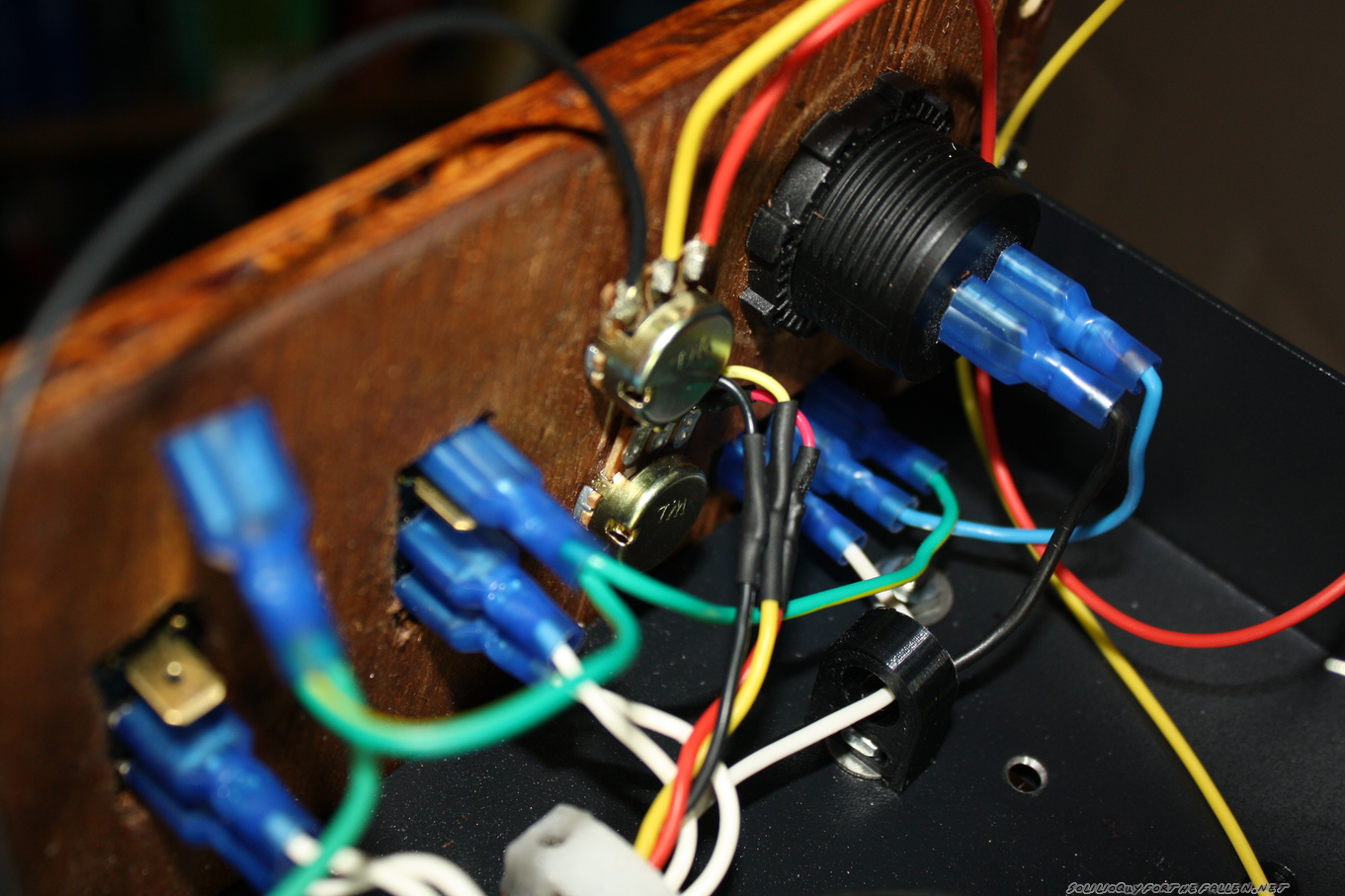
Wire Guides, Redone
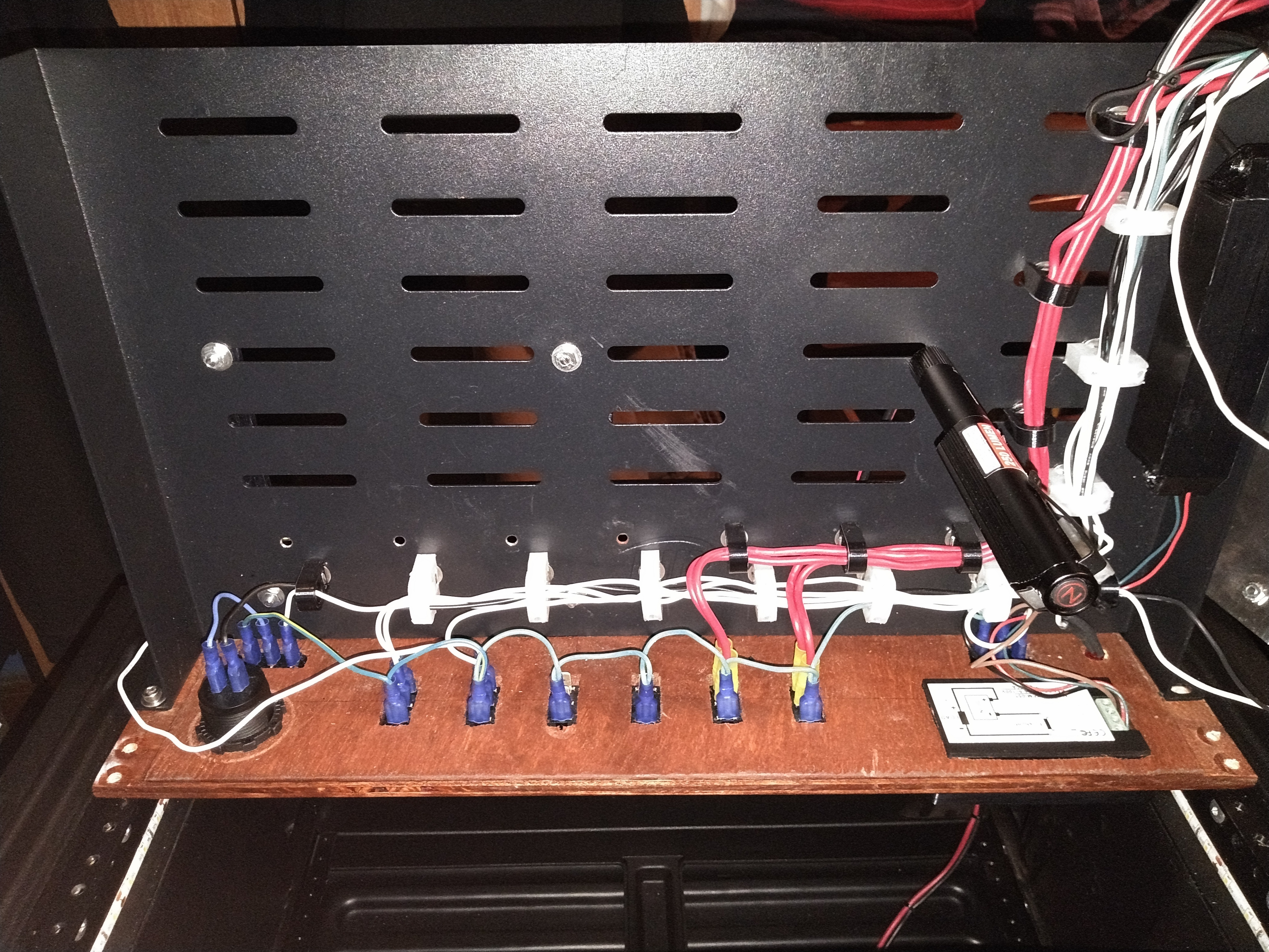
I knew the pwm modules I selected (more later) would require fitting a total of 10 new wires into the existing wire guides. The black ones designed in 2018 were filled to capacity, so I designed and printed some new ones. These were designed as two piece assemblies held together with #2-56 screws. By making the top removable, I saved myself recrimping all the spade connectors for the control panel as well as keeping having to keep the wires straight during reassembly.

Samlex SEC-1235 Anderson PowerPole Mod
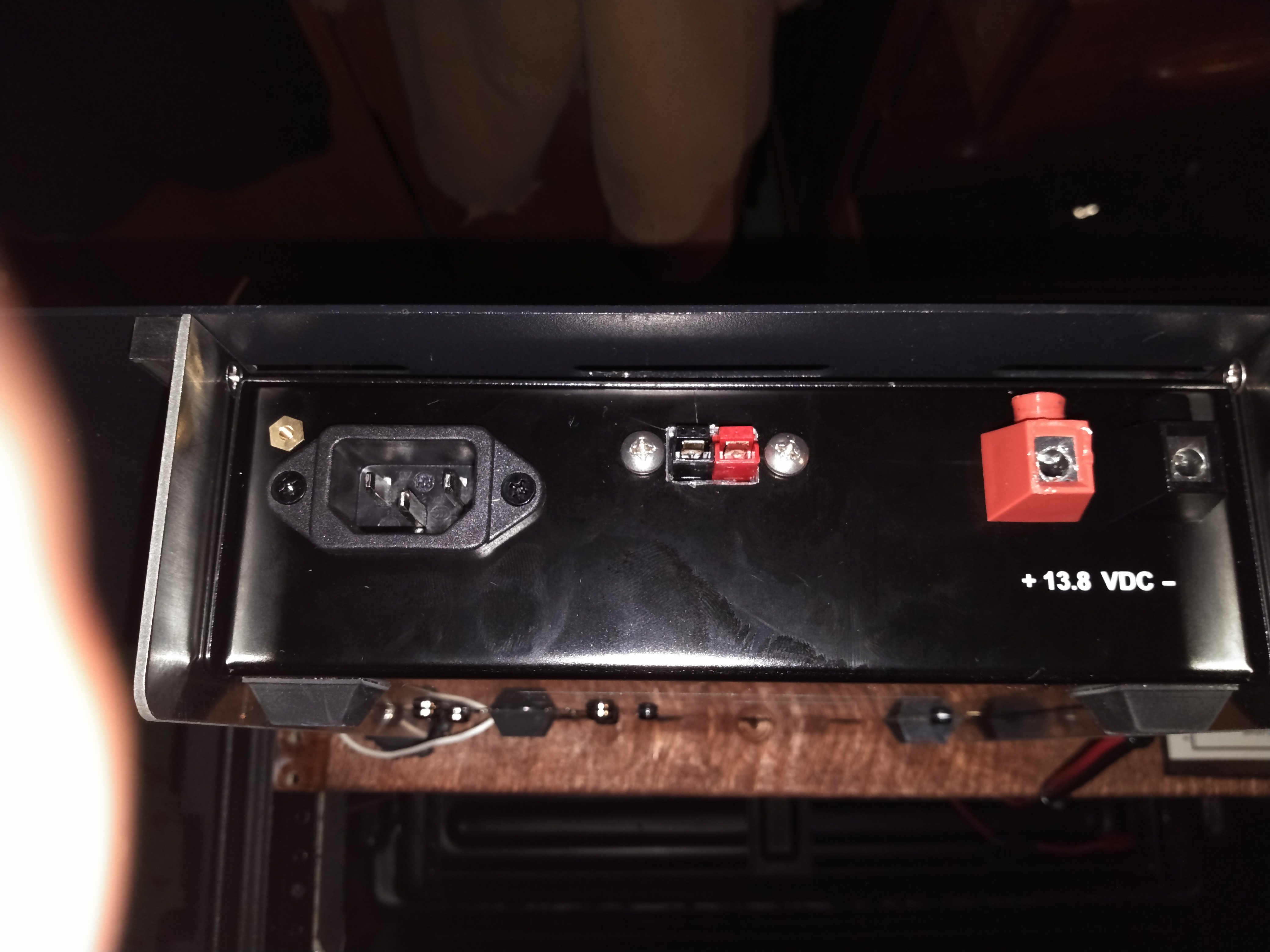
Anderson Powerpoles are the defacto standard when it comes to amateur radio power connections. My “main power feed” into my fused distribution box has powerpoles at the end. This makes it easy to swap my “feed” between the on board Samlex SEC-1235 or off board batteries or other power sources. Instead of the ugly “rat’s tail” I had rigged when I first mounted the power supply in November, I wanted to add integrated a set of powerpoles to the onboard Samlex SEC-1235 so it looked like it came that way from the factory.
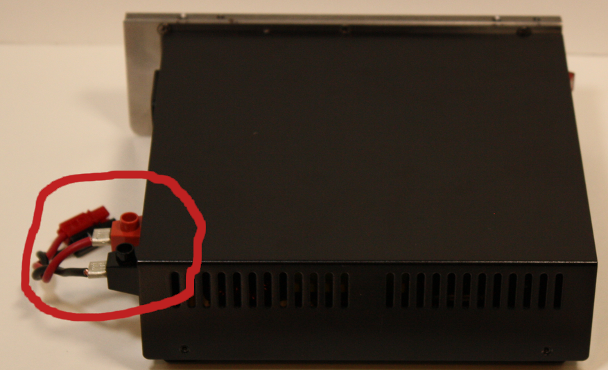
Bah!
First, I opened up the samlex and pulled the guts out. Since I would be cutting and filing, removing the internals completely was the easy way to make sure that nothing was fouled as a result. Hardened Power Systems offers the Anderson Autogrip. The idea is to press fit in the powerpoles and have a nice, clean presentation. I mounted them on the autogrip on the inside of the case to further clean the appearance. The horizontal alignment was picked by finding a free space inside the case before I removed the circuit board and marking it with a sharpie.

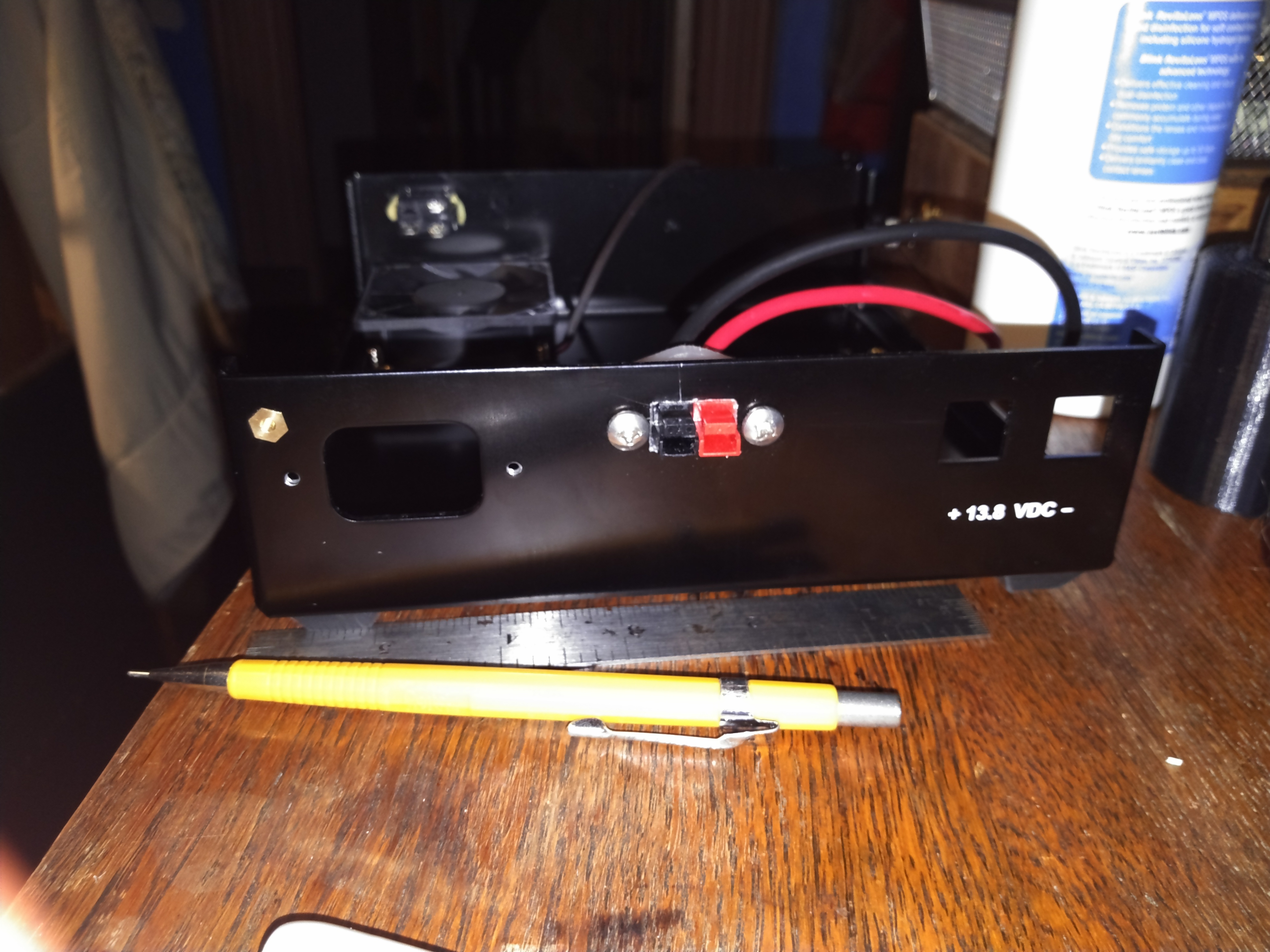
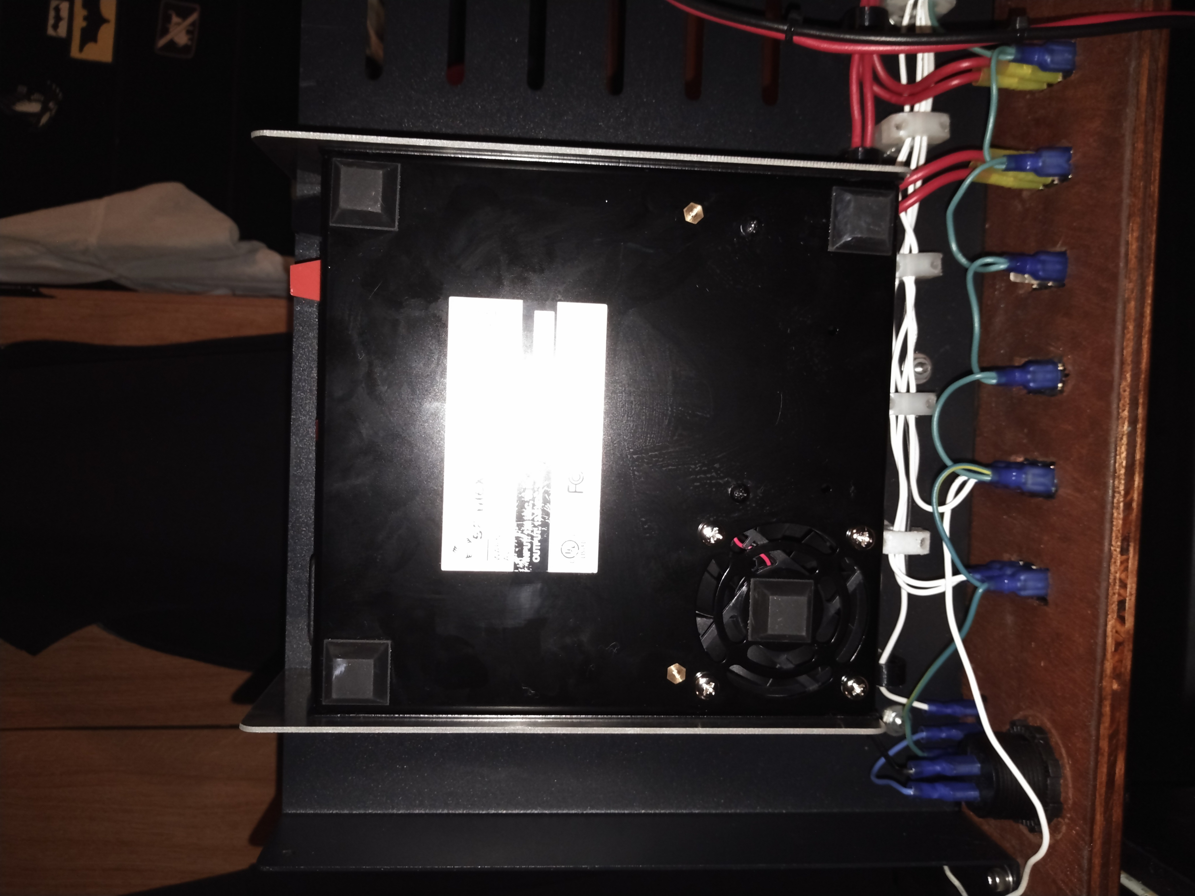
After getting the powerpoles into the autogrips and then I reassembled everything and put it back in my mounting rack. Originally, I intended for the samlex to tuck fully inside and under the bottom shelf. However, I had some empty wire guides that stopped the samlex from being able to mount that deeply. While I was swapping to the larger, two piece design I removed the additional wire guides I wasn’t using from the shelf. This gave me the extra depth I needed to fit the samlex under the shelf, as deeply as I would have liked to originally.
Mounting the PWM Modules
The primary reason for pulling the shack in a box apart this year was to add a way to control the speed of the fans and the brightness of the lights. I bought some bare PWM Modules from Amazon, knowing I could design and 3d print cases. The legs on the top hold the module down inside of the case.
 The cases were designed to also mount the PWM modules to the bottom shelf with a pressed in 8-32 nut. I thought that I would need to hold the lids on with 4-40 screws and included the holes and nut mounts but later decided that the fit was tight enough that the 4-40’s were not needed.
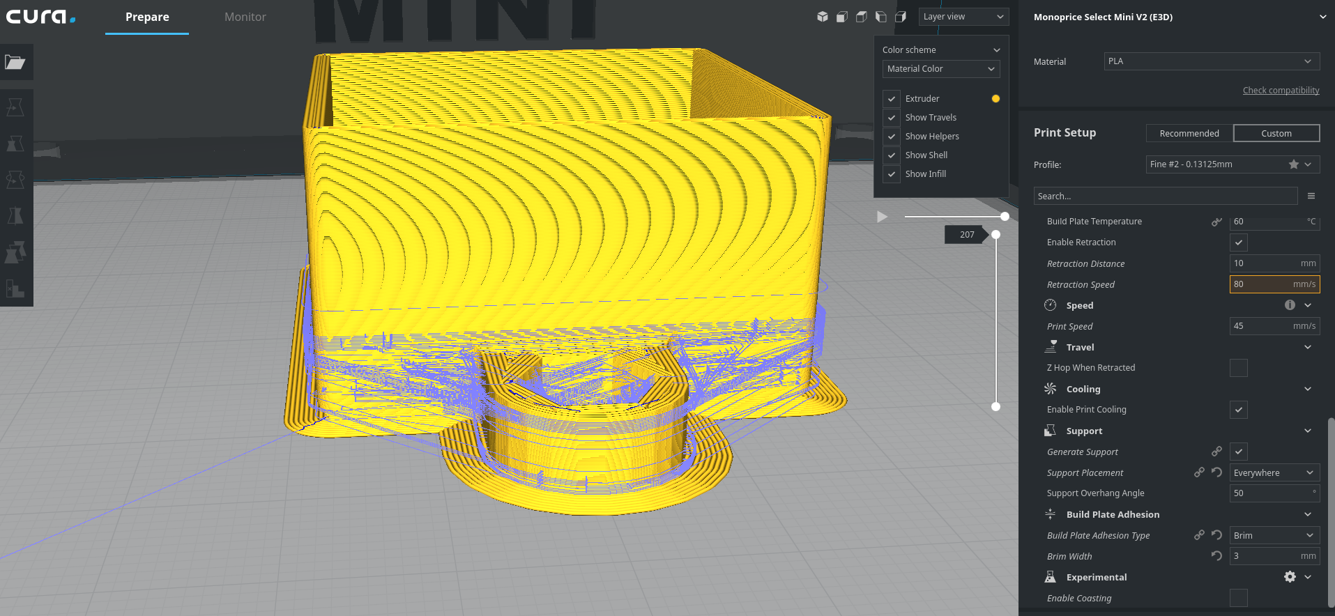
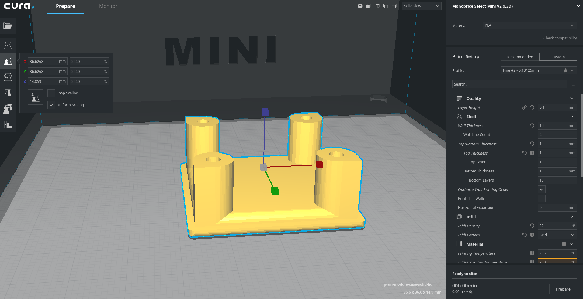
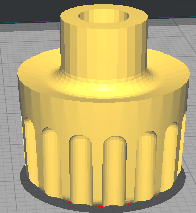
Here is the cura rendering of the box and then lid.
Mounting these was a relatively simple affair, as was connecting the wiring.


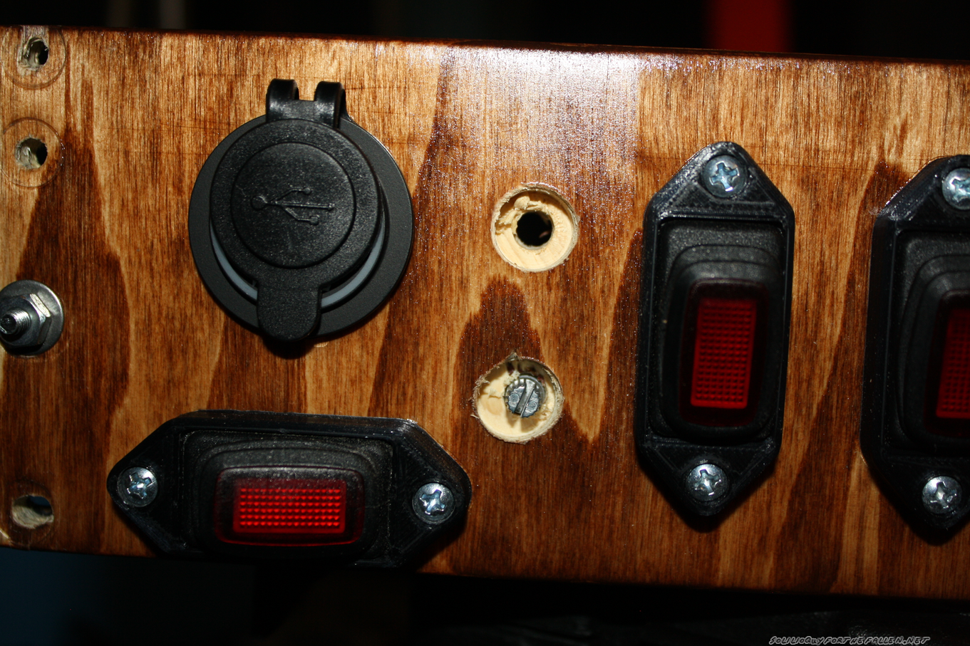
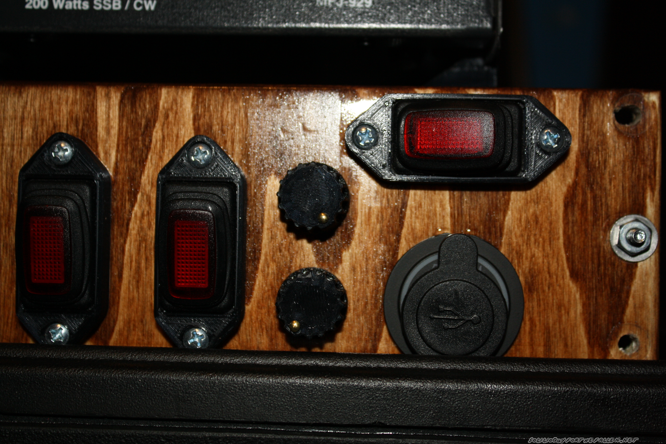
Then I needed to mount the rheostats on the control panel for access. I placed some masking tape on the control panel, then put double sided tape on the knobs. I then test fit where the knobs looked the best, and I ended up centering them between the last switch and the USB outlets. I drilled two small 5/32 holes to mark where the knobs would be.

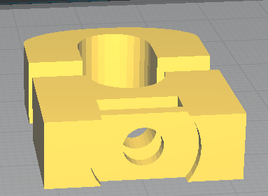
The 3/8″ plywood I used for the switch panel was actually as thick as the overall length of the thread and shaft for the rheostats. To make it work, I drilled out the front side with a 1/2″ forstner bit. I need to make some new knobs that would “hide” the deep 1/2″ hole I’d drilled. A nice, chunky, friendly knob was designed. A small hole was added so that I could press in a small brass brad nail to indicate the position. The size of the knob hides the 1/2″ hole I drilled, and has a shoulder that presses neatly onto the rheostat’s shaft.

Mounting the Signalink Mount
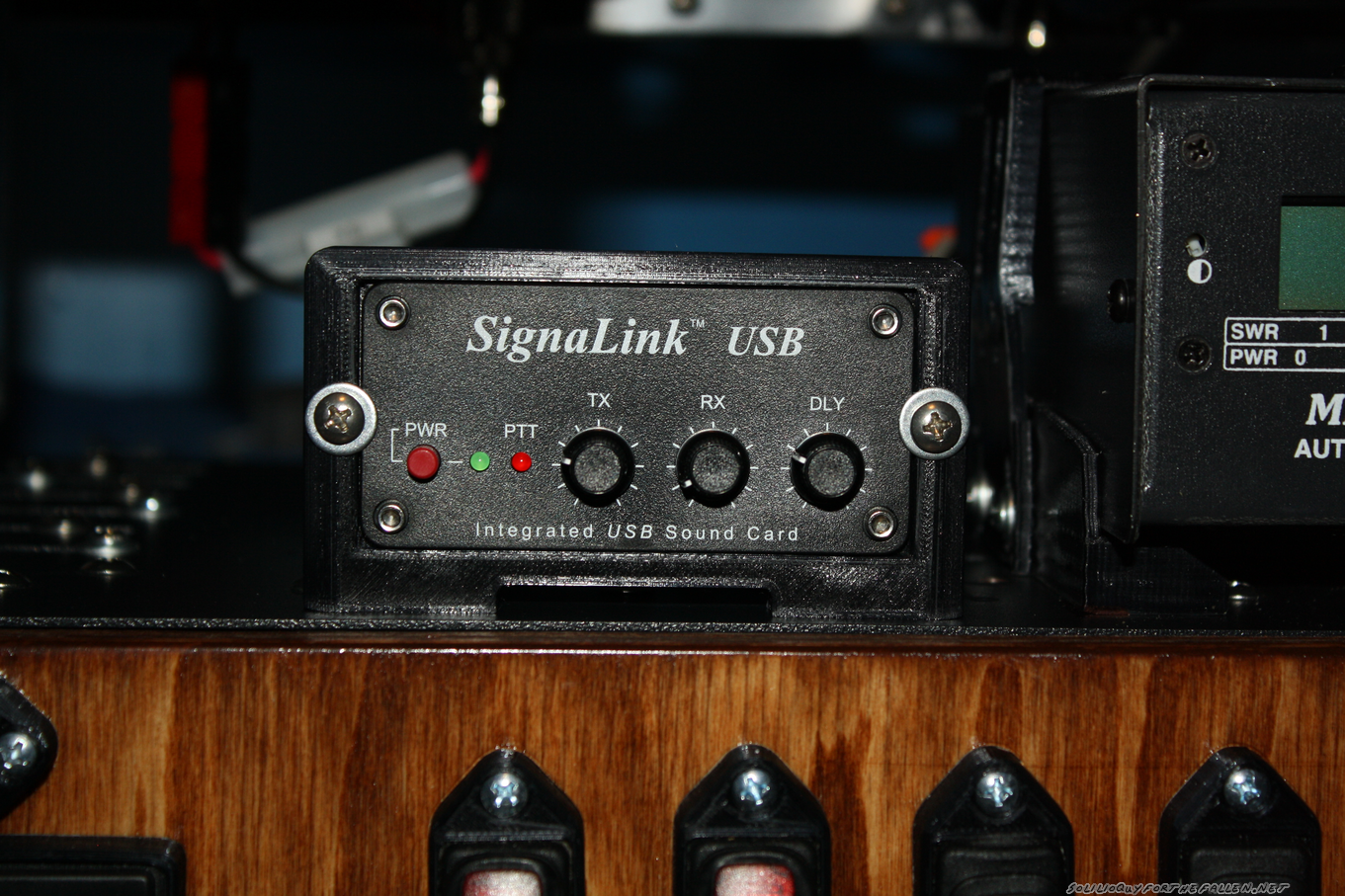
The last question was how to mount my signalink. I considered mounting it quite a few different ways but decided that I didn’t want to modify the case of the signalink in any way. So I elected to mount it from the face.

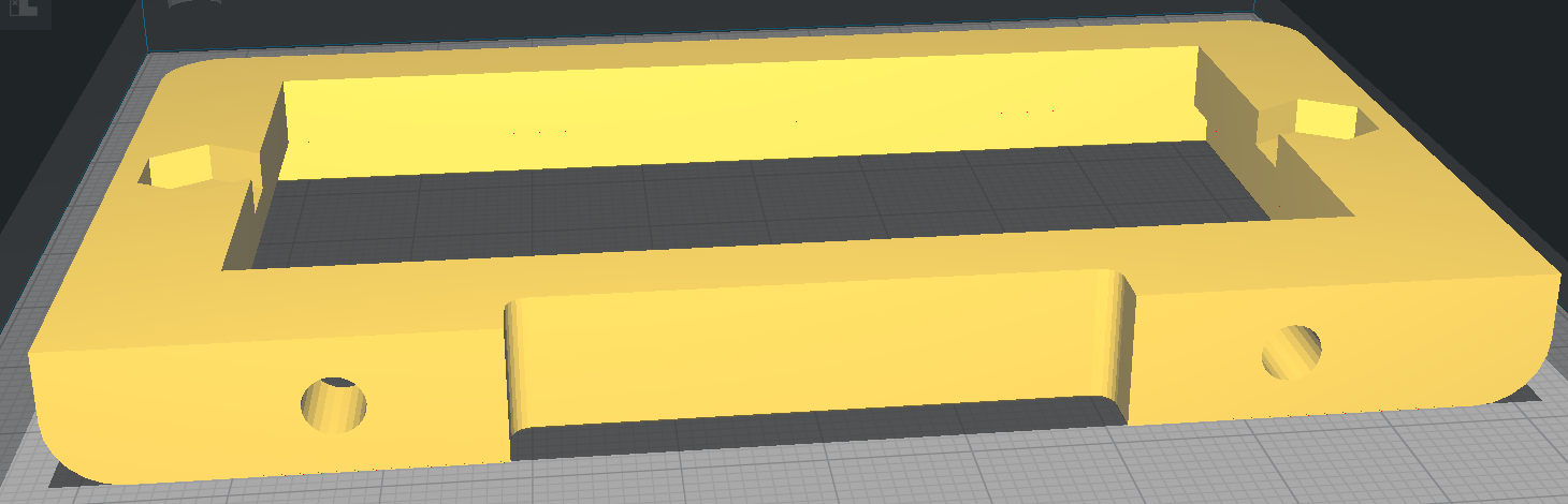
Mounting was tricky, but doable. I had to drill two new holes for the faceplate into the shelf. Then, I pushed the 8-32 screws I wanted to use into the bottom holes. The the screws and faceplate were then bolted onto the shelf. I removed the faceplate (and board) from the signalink. Then I pushed the case in from the back. I slid the faceplate and board back in. I printed this with pretty tight tolerances, so I had to push everything in square from all sides. I reattached the faceplate to the case, then used a set of 8-32 screws with washers to make sure that the signalink couldn’t push back on the front. The faceplate sits on a small shoulder on the mount.
And here’s a demo of the lights and the fans. I’ll demonstrate the Signalink in a later post.
Note: As before, I have chosen to provide many of the solid model STLs for the 3D Printed Parts I used. However, I provide these STLs without support. I may have suggestions or warnings but they are provided as is. I hope that they are useful to you, but they may not be. Free is free.