My first antenna was a simple wire dipole that I carefully measured and built as a linked dipole system so I could work multiple bands (remember that an antenna at resonance both transmits and receives energy better then one “matched” with a tuner). My first solo field day, I found out how well dipoles work when tuning to a different band (they don’t) and how troublesome it could be to mess with an erected antenna (I improvised a mast, and then had to improvise get the legs of the dipole out).
The next antenna I built was based on the W4KGH end fed antenna. Measure and cut wire, wound my first unun and then off I went with my go kit (a Yaesu 857d and MFJ-929 tuner with a cheap computer PSU to power the rig up) up to a friend’s cabin in Wisconsin. Hoisting this antenna was much easier as I only need one friendly tree and ended up with a basically a sloper antenna. I was able to cross bands easily and heard a few people working the Colorado QSO Party over that Labor Day and tuned in a Number Station as well.
The end fed antenna was employed again at my Ham Club’s 2018 Field Day where I realized that the noise I thought was from my location in Wisconsin was likely from the power supply I was using. I also struggled to get it to tune on the lower bands. Hoisting was troublesome and while I had a friendly “tree,” I was barely able to get set up.
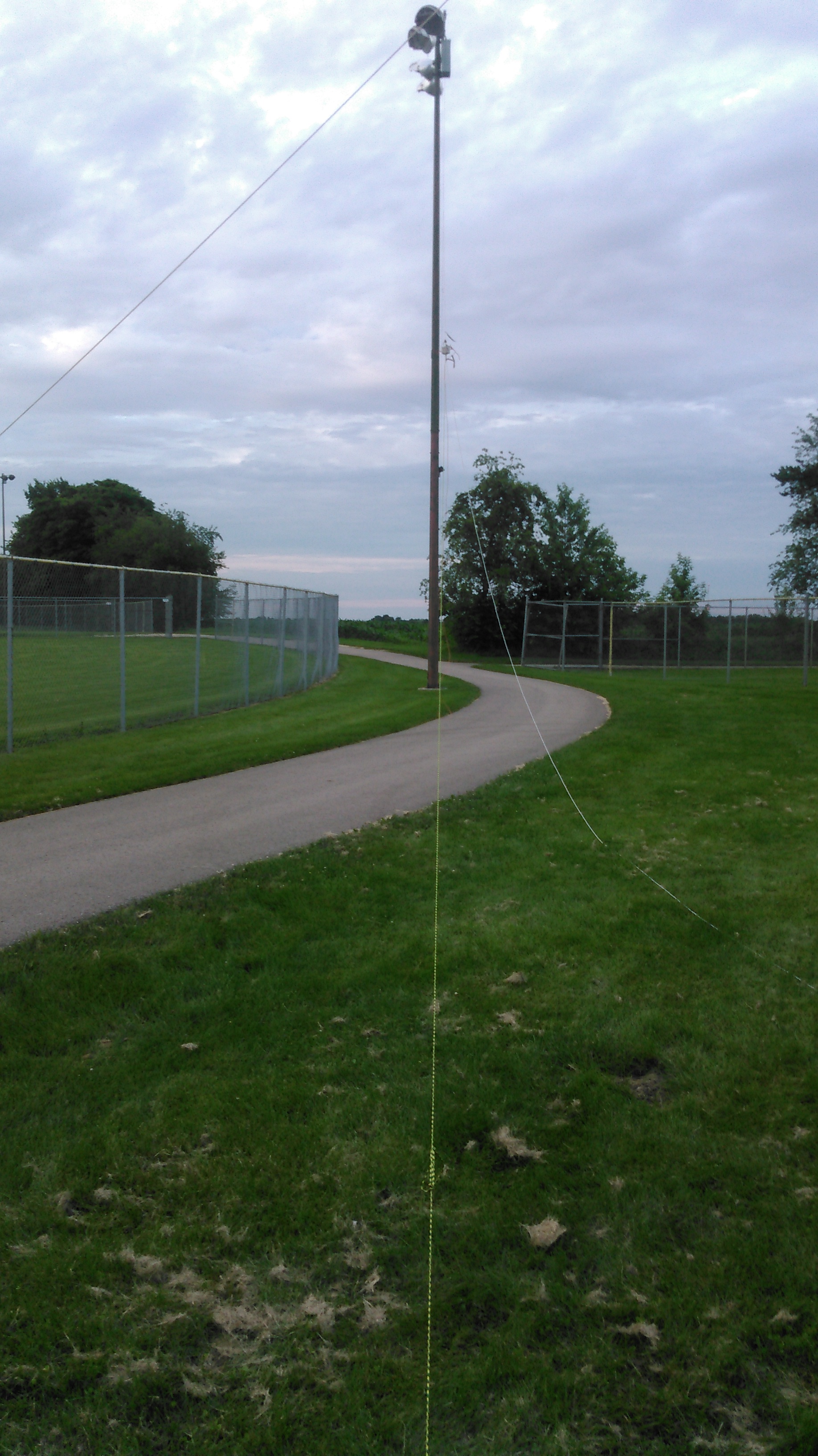
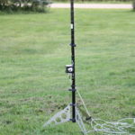
I’m a member of a Ham Radio Go Kits on Facebook, where a member posted of a slinky end fed on the group. Using a slinky as a radiating element isn’t really new. When I first started my journey as a ham, I ran across the Slinky Dipole and there was mention of the slinky endfed. What appeals to me the most about the design is the “mast” that supports it. A simple 20′ shore pole in the center of the coils of the slinky is all it takes
Due to the fact that I live in a HOA (the bane of hams) I can’t hoist an antenna permanently. There’s also a dearth of the required “friendly trees” in the area. I can get this antenna set up in under 10 minutes. Tear down is 10 minutes as well. This means I can spend more time operating then putting nonsense up in a tree.
This picture was taken before I had completed the mounting horn for the match box. Before I talk about the design exhaustively, let’s talk real quick about how well the antenna does as far as SWR is concerned. Ironically enough, the only portion of the band that this doesn’t need a tuner is for 2 meters! Below is a table of 4 SWR sweeps of the antenna. I swept the entire spectrum with a single single with and without a counterpoise and a double slinky (two slinkys I soldered together) again with and without a counterpoise. Generally a single slinky without a counterpoise is the winner, except for a few flukes. Overall, for field deployment I’ll bring a single slinky and the counterpoise but not bother to put it on. For 40m and up, this generally presents less then 7:1 SWR. If 80m is my goal, I’ll put the double slinky on and go.
 Unlike my last two projects with picture ad nauseum, I’ve picked a small subset for your viewing pleasure.
 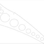 Here’s the CAD profile of the legs for the stand. These were cut with a water jet from 14 gauge stainless steel. The circles within the leg are to reduce the overall weight of the leg. The notch at the base of the leg allows me to easily stake each of the feet. Some would argue that its to heavy for the application, but the extra weight helps keep the antenna from tipping over without the stakes. I think its a good balance.
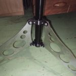 The clamps that hold the legs to the shore pole are 3d printed – as are many other things within my ham radio world. There’s some 3m double stick tape to keep them in place.
I designed the legs to pivot about the middle clamp so the top hole is drilled to provide clearance for the 8-32 bolt and lock nut that keep them in place. The top and bottom clamp keep the legs in place. For these clamps, the legs are tapped instead. The leg flips to either the deployed position or stowed and an 8-32 bolt is threaded through. This means that I don’t have to muck with a small fiddly nut in the field.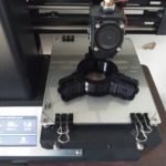 Shot of the “clamps” being printed on my monoprice.
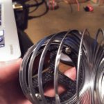
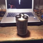 A few shots of the slinky. One showing how the caps are attached to the slinky, and then a full profile of the single slinky and the double slinky. I made small retaining straps using elastic and large buttons. The wire coming out of the bottom is to connect the slinky to the match box. I did the same sort of arrangement on both stacks of slinkies. Honestly, you don’t need to make it this complicated (in the video up top a simple lanyard clip is used but I always over complicated things.
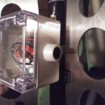
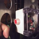
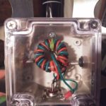 The matchbox. The banana jacks ordered were to long and were almost touching each other. I 3d printed some stand offs to try to clean this up.
 A shot of the mounting horn on the match box.
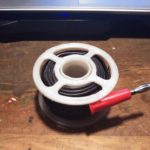
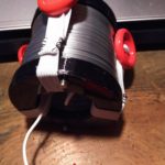
Found a neat spool on Thingiverse for the counterpoise wire (which per the above table isn’t generally needed). Printed at 50% x & y, 75% z.
