Author: admin

Puking up a Code Sample in Python

I hate python, it’s not friendly to my eyes.  That being said the compiler is super helpful.  And yes, I’m still alive despite the best efforts of …. myself.

I’m throwing together a raspberry pi zero powered uptime checker and an i2c backpack lcd display. I didn’t want to write my own library, and I wanted this to get thrown together as fast and easily as possible. Thus, I followed this guide using python. Python, ick.

But I’m not posting this to hate on anything. If I post more info on this, then I’ll share my logic for things. Anyway, one of the reasons for this display is an easy was to check the status of my DMR repeater. Here is the basic code I banged together to use the Project Halligan API that Brandmeister provides to check the status of my repeater.

Of note: Brandmeister does not provide an API call that tells you if the repeater is up or down. The website checks the last seen time and if it’s been more then 15 minutes it assumes that repeater is down. Checking against “status” or “status_text” will not tell you if the repeater is up or down merely what timeslots are linked – whether the repeater is connected or not.


import urllib.request, json
from datetime import datetime, timezone, timedelta
from email.utils import formatdate

try:
	url = urllib.request.urlopen("https://api.brandmeister.network/v2/device/313051")
except urllib.error.URLError as e:
	ResponseData = e.reason
	print (ResponseData)
else:
	lastSeen= (json.load(url)['last_seen'])
	print (lastSeen)
	timeOutTime = datetime.now(timezone.utc) - timedelta(minutes=15)
	timeOutString = timeOutTime.strftime("%Y-%m-%d %H:%M:%S")
	print (timeOutString)

	if timeOutString < lastSeen:
		print ("Repeater up")
	else:
		print ("Repeater Down")

This code isn't pretty but it does work, on my machine at least. The post however, is most certainly honest.


Radioddity GB2-D “Review”

I wanted an inexpensive DMR radio for one of my vehicles so somehow I ended up with the Radioddity DB25-D.  From what I saw it was about the best wattage for the least money once I shopped around and found it on a flash sale.  I paired the radio with an inexpensive Retevis antenna from amazon.

At the moment, my one word review is ….. “don’t.”  It’s a weird little radio with a particularly offensive “flaw” which I’ll discuss in a moment.  Otherwise, the purpose of use was to monitor my DMR repeater and to test its range in the area.  It seems as though it will suffice in that application.

So, “the issue.”  When I first set up the DMR talkgroups, I couldn’t hear anything come back – it was like the radio was muted.  But I could hear analog stations just fine.  Then I reset the radio, it set the radio to “promiscous” which is a DMR term for hearing all talk groups being broadcast by the repeated.  Which made the isssue more confusing.

What I finally determined was that unless you set an Rx group, you will hear nothing.  The solution is to create an Rx group for each talkgroup and then only add that talk group to the rx group.  It’s stupid and madness and not what the CPS guide says.

Another item on the list of complaints is though this is Radioddity’s radio and I bought it from them … it came with outdated firmware.

On to other issues: the CPS is windows only.  It’s possible to use MM7DBT’s codeplug editor in linux by using wine to run the program.  On Fedora 37 I also needed to install winetricks, then use winetricks to install dotnet47.  This will install the needed libraries and you can then run the codeplug editor.  The installer worked fine, but when attempting to run the codeplug editor I got a weird error about mono libraries.  Installing dotnet47 also install mono.

It looks like there’s ways to use serial ports in linux through wine, but a forum post led me to a python script that doesn’t work.  It’s definitely not the fault of @davidmpye as Radioddity has likely changed enough of the codeplug format so that it’s no longer compatible with the rt73.

I did find out that I can program on Fedora Linux with the Radioddity CPS.  First I needed to add myself to the dialout user group. Then I did the registry addition described here. Then, log out & in.

For posterity:

Configure the port–if the device is seen at /dev/ttyUSB0, and you want it to appear to WINE on COM1, edit HKEY_LOCAL_MACHINE\Software\Wine\Ports to have a new string entry named COM1 with value /dev/ttyUSB0

That’s all I have for now.


bass thoughts

So, I decided that I wanted to play an instrument and that I would try to teach myself to play the bass guitar. IDK, I need more hobbies like I need holes in my head (21 apparently).

I bought a used bass, and tried to set it up myself. It worked well enough, but I knew there was a ton of stuff wrong with the more I fiddled and played. The intonation kept drifting and I had a lot of buzzing from the strings hitting things. One of the first things I would need to fix was the worn nut. Tooling for that was about $150 so instead I decided that the best thing was to buy a new bass. I still want to fix the old one, but now I can learn how a properly set bass should behave instead of second guessing myself and spending more in time and effort then a replacement.

Like a few other items on the blog, these are some notes for me to self reference that I thought someone else could find useful.

Things to read

How to adjust the truss rod & action, after which you should set the intonation.

If your instrument sounds out of tune as you get further down the neck, you need to set the intonation.

Equipment I recommend

One thing that I’ve found is cheaper is not better, or necessarily versatile.

  • Fender Mustang Micro Headphone Amp. This unit can connect to your bluetooth device as a speaker. So you can play along to bass tabs from youtube or music on your phone and not worry about ground loops. As an added bonus, the amp connects to laptop via USB-C as a sound card. And I believe the music being played over the bluetooth connection streamed out to the soundcard as well.
  • Pedal Tuner. Seems to work well enough However, it isn’t the best for intonation, and you need a battery and cable.
  • Stroboscope tuner is the standard for intonation (and with a price tag to match). But you may as well put the $30-$75 for a cheap tuner towards this and be done.
  • Bass strap. I just liked how this one looked.

Equipment I Hate

Other Misc Stuff

Have I mentioned I don’t really know anything about playing or working on the bass? I’ll figure it out.


Historical Evidence for Asking Questions

Over the last few years I’ve heard a lot about how we need to “trust the science,” “trust the government,” etc.  Here is a compendium of reasons from reasonable sources (or well cited) that we should always ask questions.  I’m not saying that in every case below people were purposefully acting maliciously, although the Tuskegee Syphilis experiments definitely qualify, but if no one had challenged and questioned …. what would have happened?

I would like to point that as a child I was taught that science never solved anything.  And that by questioning the tests you strengthened the results.

The cases below are offered for your perusal, interpretation, and consideration into “asking questions,” which is not always the same as challenging authority.  The constitution and law has given us a process to challenge authority and it should be followed.

  1. https://en.wikipedia.org/wiki/Buck_v._Bell
  2. https://en.wikipedia.org/wiki/Agent_Orange#U.S._veterans
  3. https://www.cdc.gov/tuskegee/timeline.htm Tuskegee Syphilis experiments
  4. https://helix.northwestern.edu/article/thalidomide-tragedy-lessons-drug-safety-and-regulation. Thalidomide was a “wonder drug” for babies, and then they started being born short limbs.
  5. https://en.wikipedia.org/wiki/Catholic_Church_sexual_abuse_cases
  6. https://en.wikipedia.org/wiki/Operation_Mockingbird
  7. https://www.businessinsider.com/army-sprayed-st-louis-with-toxic-dust-2012-10
  8. https://www.smithsonianmag.com/history/spoonful-sugar-helps-radioactive-oatmeal-go-down-180962424/
  9. https://www.nhregister.com/news/article/Shocking-medical-experiments-are-part-of-U-S-11573849.php
  10. https://www.cidrap.umn.edu/news-perspective/2002/11/gao-military-anthrax-shots-caused-many-reactions-prompted-some-pilots-quit. As a side note, review this. It states, “About 20 percent of those infected will develop difficulty breathing and a bloodstream infection that causes death. If treated with antibiotics, less than 2 percent of infected persons will die.” This is not for inhaled anthrax but for blood infection anthrax. The risk profile is so low that mass vaccination is not recommended. If anthrax becomes a used bioweapon the threat profile would change, though thankfully the vaccine appears to protect (per the Children’s Hospital of Philadelphia link above) against inhaled anthrax as well. This is why military personnel heading into a high threat profile are vaccinated.
  11. https://www.atomicheritage.org/history/human-radiation-experiments. Plutonium injections into 18 individuals, who were not informed of the injections.
  12. Kellog’s Asthma Relief
  13. COINTELPRO, illegal wiretapping and alleged assassinations. COINTELPRO style operations are alleged to continue into today according to the article.
  14. Ruby Ridge, combined with WACO which forced the United States government into “compliance” with their own laws – funny how that works.
  15. While it might be unfair to say that the government poisoned drinks during prohibition, they did add poison to various alcohols not intended for consumption.  An allegory would be adding laxatives to Scope mouthwash.  https://www.usatoday.com/story/news/factcheck/2020/06/30/fact-check-u-s-government-poisoned-some-alcohol-during-prohibition/3283701001/

This will be a rolling post, updated as I feel relevant. 


Dutch Apple, Please

Let’s start by recapping my experience with the models and operating systems to frame the discussion.  I’ve actually dealt the majority of the models, and my opinion is much the same on all of them.

Version Comments Operating Systems
2B+ I experienced stability issues and burned up two usb wireless cards.  I worked with the Pidora OS primarily, but eventually gave up and switched to Raspbian.  This did not make it any better as I can remember. Pidora & Raspbian
3A/B The only one I actually “like.”  Excellent for RetroPie and Octopi.  I haven’t used the Raspbian base OS. Retropie, Octoprint
4B I really hate the Pi 4.  Its not much of an specifications improvement over the 3B as far as I can tell.  I haven’t worked with mine enough to know though.  However,  I’ve already corrupted (and destroyed) one SD are a result of the power supply issues present in every single iteration of Raspberry Pi.  That leads to my main complaint about the Pi 4.  Why implement USB-C but not have it negotiate to any of the higher voltage options? Retropie
Zero W Its okay.  The SD cards seems to get corrupted often but they aren’t often destroyed.  Overclocking seems to work different on every single board I’ve bought.  Also, my first ZeroW would segfault when I tried to use the wireless connection. Retropie, Pi-KVM, PiStar
Zero W<2/td>

A very welcome update to my Retroflag GPi. Sadly, since its a new system I set up and clean install and by then I was done playing with. I will say though, I wish I had bought 2 of them. It seems stable enough, and I need to take the time to play with it more.


My main beef with the Pi family is that needing a 5.1 volt USB power supply defeats the purpose of using USB to power them.  Add in the awful time I had with the 2B (and the Alfa Alfa AWUS036H that it ate) I’m not really thrilled with them  I’m sure someone will say that by using a properly rated power supply all my problems could be solved.  However, I would argue that if you need a “special” voltage spec, then use a 9VDC or 7.5VDC barrel jack and step down the voltage on the board.

What prompted my post about this an article posted on Hackaday about modify the pi to try to help with the voltage warnings.  My opinion is this: Pi’s are not USB devices.  A wide variety are arguments were made in the article’s comments.  They’re enlightening, but ultimately I think you know the ones that I agree with this.  The Pi5 should feature a barrel jack instead of a USB.  There are a bunch of ways to try to help with the problem but at the end of the day if you put a USB connector in people will use whatever USB they have handy.  The legrand USB outlet I installed at my desk provides 4.87 volts which is with the USB power specification.  It can power a pi zero, and usually a 3B.  However it will completely kill an SD card on the Pi 4.  Even the USB-C charger (that will auto negotiate to 9VDC or 12VDC) cannot power my Pi4.

I loved my 3B retropie setup and in general I’ve been satisfied with the Pi3 devices I’ve deployed.  Using octoprint has been fantastic – I can now monitor my 3d printers remotely from work.  But I’m not sold on the other models.  Here are a few other tips for a less frustrating Raspberry Pi experience.

  • Don’t back up your home directory or configuration files.  Create a complete image the card using dd or follow HowToGeek’s instructions (I don’t run windows in that capacity).  If the SD card dies you flash a new one and go.
  • Don’t use a Pi’s when what you mean to use is a microcontroller.  Arduino, teensy, atiny85 are all more stable (and less money).
  • Don’t use pi’s when you could run a virtual machine instead.  You may even find it useful to spin up a copy of Fedora or Ubuntu server on an old machine.
  • Don’t use them for “mission critical” tasks.  Setup a “hot swap spare”.  $35 for the pi & imaging an SD card over is nothing.

Long and short, if I need to deploy a pie make mine a dutch apple.  By that I mean be cognizant of the limitations and strange requirements of the system and don’t try to get outside of them.  If I use a pi I know exactly what I want and why.

Update 20220417: Comment on the ZeroW2


Trials and Tribulation of my Anet A8 Back Online

Backstory ….

I bought this thing in early 2017, and was never quite able to get it running.  At the time, it was mostly do to my inexperience with 3d printers.  I ended up buying a Monoprice Mini on Black Friday, and there’s quite a few projects on the blog detailing my usage.  At the beginning of the year, I started having trouble with my monoprice. I was thinking about getting a prusa mini, but decided to that it would be a better idea to bring this back online.  I already had the Anet (just never quite got it functioning) and it had a much bigger bed.  What could go wrong, I asked myself.

So, my “process”

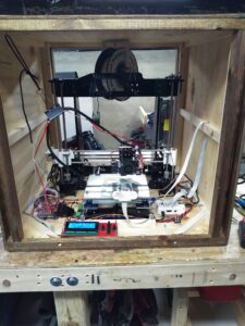
The biggest issue with the Anet A8 as I purchased it was that the bed didn’t stay flat.  So, I built a wood cube to both store it in and help keep the flat down.

In the anet OEM firmware, when a thermistor dies the firmware turns the heaters on to try to ramp the temperature up.  This could result in the printer trying to burn your house down.  So, I tried to install the marlin firmware following this guide from all3dp. I had trouble compiling the firmware, but in the process of trying to update the firmware I managed to wipe the board.  So, I had to figure out how to recover the firmware.

A brief guide to recovering the firmware on the anet board

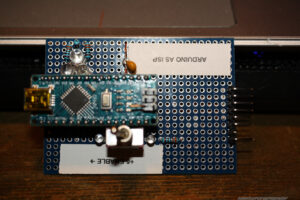
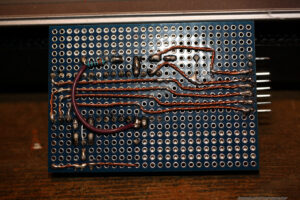
Anet doesn’t burn the bootloader to the board, so to be able recover/upgrade the stock firmware you’ll need and ISP programmer.  While ISP programmers with specific headers are available at various places, I wanted this now at 1AM on Saturday. You can press an Arduino Nano into service as an ISP programmer: http://www.martyncurrey.com/arduino-nano-as-an-isp-programmer/

One modification I made was to put a 1PDT switch inline with the 5 volt power line of ISP programmer so that I could isolate the Arduino (and this my computer) from the Anet’s board.  You could use the switch, or make sure that you aren’t powering the board from the wall while burning the firmware.  Make sure you tie the reset pin on the arduino to GND with a capacitor otherwise you’ll get a weird error that means nothing – in my case one of the three checksums would be correct but the rest would fail.

The design is kind of overkill, but I always seem to get myself into trouble and need random things like this.  Next was to build an ISP header to match my board to the anet ISP header.  I found image below on instructables.


After that, connect the arduinoISP to the isp header.  Start the Arduino IDE, and use the “Burn Bootloader” function in the IDE.

I still couldn’t compline the marlin firmware (compilation errors), but wanted to get the printer up and running so I decided to reinstall the oem firmware which is/was available at the Anet website.  Anet distributes a hex file, so off to the command line to flash the firmware

~/arduino-1.8.12/hardware/tools/avr/bin/avrdude -c arduino -P /dev/ttyUSB0 -p m1284p -b 115200 -U flash:w:A8_chuchang20160525.hex a -C ~/arduino-1.8.13/hardware/tools/avr/etc/avrdude.conf -v -v -v -v

Can I print yet?

Technically, yes by running an SD card I could print.  However, I’ve started to really like printing with OctoPrint in control.  Remote control, better file management, onboard webcam.  Mix in a relay to control power to the board (which I had to modify to use a car relay because the anet uses more amps then the stock relay on the board).

setup octoprint to control the relay by some custom mixing in the yaml file

Originally, I had the camera mounted to the ceiling of the cube, but I couldn’t tell if a print was lifting or not. I also had an issue where the filament bound and I wasn’t able to detect an issue from the ceiling.  So, I made an from some 3/32″ tig wire so that as the z axis rises through the layers, the camera maintains a view of the nozzle. Depending on how fast the nozzle is moving I can get some shaking in the camera but I’m not trying for an instagram quality video feed.

I was still having a problem with the print lifting off the bed.  At that time in the basement, start up temps are 5/6°C (42°F).  While the bed and nozzle maintain temp, the rest of the print doesn’t.  I added a panel to the back of the cube, and a door to the front.  This seems to have solved the lifting problem.

I also built a hanger for the filament spool in the cabinet.  So far, its working great.

But can I print yet?

I did run a number of prints.  However, one night I again experienced trouble with getting the bed up to temp.  And here is what I discovered:

The bed connectors are technically rated for the load, but have gone bad. So, the printer is once again trying to burn my house down.  So, off to Grainger for a suitable replacement. I went with these screw terminal connectors.

We’ll see how these work out.

So you can print now, right?

Yes, but I still want to get the marline firmware installed on the board. However, I think I’ll put that in a new blog post once I manage to accomplish that.

Final thoughts:

I should have bought the prusa.


A Useful Gadget

The problem though with developing on an arduino is there’s not a real good way to debug it, other then lots of printing to the serial port.  So, not a “problem” – unless you can’t get a computer near what you’re working or you want to air gap your very expensive laptop from the arduino.  How to solve this?

JeeLabs has developed firmware for the esp-12s to turn it into a wifi serial platform.  I think its out of active development at this point, but it still works – and pretty well at this point.  So, I built a breakout to the esp-link.  And feature creep occured.

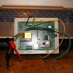
This isn’t something I really want to sell or build or what have you.  But I decided today while I was debugging the “LazyVac 31” with this that I would share it for everyone, for free.  Because I can – and because I think its that useful.  Since this post is for the developer amongst my readers I won’t deep dive to much.  Instead, I’ll link the relevant components and share the schematics, stl, and some pictures of the finished project.  If you need more details, feel free to ask in the comments.

The Finished Project. Yes, Full Rebel XS + Macro Lense Resolution

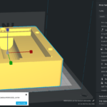
Cura View of the Carrier

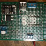
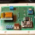
Top View of the Board

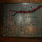
Bottom Side of the Board

Schematic Diagram

Carrier STL

Additional Notes

  • The USB A on board is for power only.  I have a breakout board that plugs into a USB power supply so it makes sense to be able to power the breadboard.
  • From what I can tell, the esp12-s is meant to run on 3.3VDC.  So, since I had to include a 3.3VD rail it makes sense include a screw terminal for 3.3VDC powering.
  • I added the silicone wire and clips after I built the schematic.  I found out that being able to hook up the two wires with the test clips made my life super easy.
  • I generally use my phone to connect to the esp-12s’ wireless access point and then connect to the serial terminal via JuiceSSH.
  • The extra holes on the top of the carrier are meant to have 12mm magnets pressed in for retaining a cover but I’ve never needed the cover enough to design one.

Components

Flashing the Firmware

This is the command I used to flash the firmware via my frog pin programmer.  You’ll need to download the esptool package for your platform to flash the firmware.  Its much easier then tying to get the Arduino IDE to flash the firmware via the programmer.

esptool-2.8/esptool.py --port /dev/ttyUSB0 --baud 460800 write_flash -fs 4m -ff 40m 0x00000 esp-link-v3.0.14-g963ffbb/boot_v1.6.bin 0x1000 esp-link-v3.0.14-g963ffbb/user1.bin 0x7C000 esp-link-v3.0.14-g963ffbb/esp_init_data_default.bin 0x7E000 esp-link-v3.0.14-g963ffbb/blank.bin

esp-link Firmware


An Update. Not too notable.

Hrm, what to update on?  My last post was released roughly 4 months ago.  Who could have imagined where we would be today?  Corona is … mostly a ploy to destroy the economy in the wake of the November elections.  There are some real medical issues that could be present but its to the same group of people who are vulnerable to the seasonal flu.  Its time to get back to work America.

Having addressed that … what else is there to talk about?  Let me rummage about here.  This is more of a scrap bin update so … things might be rough in places.

Projects

The biggest change is that I have a new shop.  I would love to post pictures but operational security and all.  The new shop gives me better capabilities.  I’ve also expanded what tools I have on site.  A basic stick/tig welder, lathe, and work bench are all welcome additions to my capabilities.  I’m looking forward to starting my own business and maybe escaping from the nonsense that is corporate America.  My sales site is already listed on here, but for kicks, check out my offerings at underthebedstudio.com.

I also built a painting cabinet that helps keep the fumes down in the house and give excellent finishes to parts I need to paint.  One of the first projects that I used it for was a drive over antenna base.  My intention to use this at the remaining service events this year that don’t get cancelled as a result of the Panicdemic.

Another cool project I worked on was a Cigar Punch.  With my 3d printer I was able to iterate through designs pretty quickly.  I threw out the iterations but took a picture first:

Only took me 6 tries to get to the form factor I was happy with.  I also finally found a pre-hardened material to make the punch itself from (drill bushings), which was the cause of Mk4 & Mk 4.1.

While I was looking at a few things, I ended up buying an ESP-12s which I found prebuilt firmware that would let me use it as a serial port over wifi.  Pretty sweet.  So here’s my interpretation of it:

Here’s the Schematic for the protoboard above. It uses an 18650 cell under the board for powering everything. And here is the STL for the carrier. I used standard 8-32 screws to hold the protoboard down.  The charger circuit chip is here on Amazon.

Computer Jazz Hands

A few computer things that I’d like to talk about.

First up is the Retroflag GPi.  This is a pretty slick little box that takes a Raspberry Pi Zero (Wireless if that’s your thing) and turns it into a self contained Retropie gaming machine.  Being that its a Pi Zero, it struggles with anything over Super Nintendo but works pretty well for lots of other things.  If you’re into gaming I highly recommend it.  I just wish every single pi unit with the exception of the Pi3 wasn’t so damn finicky.  I do have scripts that allow me to turn off the wifi and the bluetooth and also rsync over wireless.  Code at the bottom.  One thing I would recommend to everyone – just get a bluetooth keyboard at the same time.  Normally I would recommend a 2.4ghz USB keyboard (I’m a fan of this one) but with the Pi Zero and the GPi case – bluetooth is best. I ended up with this one.

Ah, the Hak5 Jasager.  They released the firmware 2.4 for the Mark V a month or so ago.  I hate to say it, but I’ve never really gotten the thing to work as well as I would like.  I’m always fighting with it, and it seems to be always corrupting sd cards – which kills my plugins.  At this point, I would be hard pressed to buy the Mark VI.  Hak5, thanks for all you’ve taught me.  Best of wishes.

What about a Pwnagotchi?  A wifi auth key hacking tomagotchi?  Sweet.  But my dislike of RasPi’s still applies.  Also, its 2020 and now that I ponder the idea – I only see a couple of wifi configurations in the “wild.”  The first is with a proper WPA2 password which can be tricky to catch and crack.  The other is a captive portals with open associations.  And no, fortune 500 employers and authentication portal doesn’t secure the traffic of the users.  With open associations, no reason to associate.  Just grab it from the air.

I built myself a FreeNAS box last year as well.  This makes it super easy to back up my laptop across the network.  A few recommendations

  • Wire your network.  Seriously.  The speeds of a wired 10/100 easily exceed the speeds of wireless.  While you’re at it, this is an excellent time to learn how to make your own network cables.  Pick up a 100′ Cat5e cable and a crimpers + ends and go to town.  Custom length cables make management much easier.
  • Put in a “dumb” gigabit switch between your main computer and the freeNAS.  I bought this one, but I couldn’t tell you if it would better then any other.  Going to gigbit?  Amazing.  Most files get transferred before a status window can open.  And backups – ironically 10 times faster.
  • RAID.  RAID all the things!
  • And, do yourself a favor.  Get a cheap UPS to put the freeNAS on so minor (or major) power outages let it fail gracefully.
  • Having a well spec’d FreeNAS box lets you run servers all the time.  I have one that starts up to handle my DNS requests.  I’m running the Pi-Hole distribution because I’m not a fan of ads.  Or the tracking nonsense that they do.

Getting a FreeNAS box set up was awesome.  I highly recommend it.  Right now, I’m loving everything about it.

I’m still running Fedora 30 on my laptop.  I’ve never really booted to the Windows 10 installation that came with it – just to shrink the partition and I’m considering getting rid of it when I update to Fedora 32.  I’ve held out against Fedora 31 long enough that I think I’m going to wait for 32 now.  I usually do a fresh install.  To many things can get muddled when doing an update and a fresh start it always nice. Probably make an image of the HD again before I wipe Windows 10 though.  Shout out to Clonezilla.  Thanks guys!

Miscellaneous Topics

Affiliate Links.  There’s still no affiliate links here on the blog, and there will probably never, ever be unless the players change their tune.  As I figured, they’ve started to weaponize the Terms of Service and its just not worth it for the little money.  If the Youtube Adpocolypse can hit somebody like Demolition Ranch …. it will happen to anyone.  Free Speech is important – don’t let yourself get caught in the trap.  By the way, COVID-19 is totally Commie China’s fault.

Social Distancing.  Ugh.  Seriously?  Why did it take this for people to realize that door knobs, pin pads, and people are nasty?  They’re just nasty.  And, stay the hell out of my face.  COVID or not, I don’t want you within reach.  Just back off.  If you’re close enough that I could reach out and kick you … maybe you should back up just a touch.

Drones.  I would love to get a TinyWhoop with FPV.  I think it could be super useful and handy.  But then I look at my other drones that I never touch and convince myself its to much.  Drone guys, keep it up.  I’ll have to live vicariously through your youtube videos.

Macro Lens.  Why did I not buy one of these before?  They are super awesome.  I’ve messed with macro tubes, but they don’t work as well as a macro lense does.  I highly recommend buying refurbished lenses and flashes directly from Canon.  They’re a little more (like … $20) then what you would find for used prices, come with a warranty, and free shipping.  I’ve always been super happy with Canon equipment and their repair shop.  Seriously though, is this not gorgeous?  Having a macro lense is great for documenting any of the fiddly things I do, like below.  And honestly, I can see it being “one lense to rule them all” for me.  The kit lens is a close second.

I recently went through an purged my youtube subscriptions.  I think I got rid of half of them – many had been deleted or I no longer watched them.  A few channels to shout out:

  • Andrew Klavan – I love his satirical intros.
  • Marling Baits – He makes fishing baits, and good videos just to have playing.
  • This Old Tony – Dad Jokes and Machining.
  • AVE – irreverant as f*ck.
  • Ivan Miranda – massive scale 3d printing projects.
  • Project Binky – in Colour! Dry british humor, and the only car show I’ve ever liked.
  • Townsends – this man would have killed it on PBS when I was a kid.

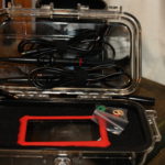
The DS213 o-scope.  Not a bad little device.  Short on features, but for the price tag not a bad deal either.  It let me see some things I couldn’t see with my multimeter.  I have a proper oscope I need to repair, but to be honest I’m scared of the high voltage that’s inside.  I found a drybox case online that holds this and the probes perfectly.  Standard USB charging nonsense.

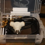
While I’m at it, check on the NanoVNA.  I’ve only really used it for checking SWR but there’s apparently a ton more that it can do.  Here’s my kit, with the adapters I’ll need to get it to work with my equipment.  As big as my go box and antenna setup is, its nice to know I can through this in my messenger bag or goruck with my laptop and be able to make some quick checks.  This does standard usb charging as well but it wants a USB-C cable but doesn’t implement the fast charging spec.  A waste.

Other Life Stuff

Still need to get digital working in my go box.  Hopefully taking the time this week to put my HF rig on a dummy load and do the experimenting that I need to do.

I could really use a vacation.  Somewhere tropical, sunny, and hot would be nice.  Maybe via a cruise ship?  Prices went through the floor now …..

Mentioning drones and how its not really something, I’d really love a Yaesu FT-818.  Oh well, I probably wouldn’t use that either.

In Closing

Rock on folks.  I’m going to peace out for a bit.  Hope you enjoyed the randomness presented above.

RetroPie Scripts

Make a folder in the RetroPie roms directory called “bash” – mkdir -r ~/RetroPie/roms/bash

Copy over bash scripts. I have scripts for enabling and disabling the wifi adaptor, as well as using rsync across my LAN for rom directory syncing

Copy bash-mod/configs/bash into /opt/retropie/configs/

Copy over bash-mod/theme/bash into /etc/emulationstation/themes/carbon (or whatever theme you’re running is)

sudo /etc/emulationstation/es_systems.cfg and add the following code to the <systemlist> tree:

						<system>
							<name>bash</name>
							<fullname>Bash Shell</fullname>
							<path>/home/pi/RetroPie/roms/bash</path>
							<extension>.sh .SH</extension>
							<command>/opt/retropie/supplementary/runcommand/runcommand.sh 0 _SYS_ bash %ROM%</command>
							<platform>bash</platform>
							<theme>bash</theme>
						</system>

Restart Emulation Station

bluetoothdown.sh

#!/bin/bash

sudo rfkill block bluetooth

bluetooth-up.sh

#!/bin/bash

sudo rfkill unblock bluetooth

wifi-down.sh

#!/bin/bash

#sudo ifconfig wlan0 down
sudo rfkill block wifi

wifi-up.sh

#!/bin/bash

#sudo ifconfig wlan0 up
sudo rfkill unblock wifi

Yet Another (Clever) End Fed: AKA The Slinky Antenna

My first antenna was a simple wire dipole that I carefully measured and built as a linked dipole system so I could work multiple bands (remember that an antenna at resonance both transmits and receives energy better then one “matched” with a tuner). My first solo field day, I found out how well dipoles work when tuning to a different band (they don’t) and how troublesome it could be to mess with an erected antenna (I improvised a mast, and then had to improvise get the legs of the dipole out).

The next antenna I built was based on the W4KGH end fed antenna.  Measure and cut wire, wound my first unun and then off I went with my go kit (a Yaesu 857d and MFJ-929 tuner with a cheap computer PSU to power the rig up) up to a friend’s cabin in Wisconsin. Hoisting this antenna was much easier as I only need one friendly tree and ended up with a basically a sloper antenna.  I was able to cross bands easily and heard a few people working the Colorado QSO Party over that Labor Day and tuned in a Number Station as well.

The end fed antenna was employed again at my Ham Club’s 2018 Field Day where I realized that the noise I thought was from my location in Wisconsin was likely from the power supply I was using. I also struggled to get it to tune on the lower bands. Hoisting was troublesome and while I had a friendly “tree,” I was barely able to get set up.

I’m a member of a Ham Radio Go Kits on Facebook, where a member posted of a slinky end fed on the group.  Using a slinky as a radiating element isn’t really new.  When I first started my journey as a ham, I ran across the Slinky Dipole and there was mention of the slinky endfed.  What appeals to me the most about the design is the “mast” that supports it.   A simple 20′ shore pole in the center of the coils of the slinky is all it takes

Credit where due

Due to the fact that I live in a HOA (the bane of hams) I can’t hoist an antenna permanently.  There’s also a dearth of the required “friendly trees” in the area.  I can get this antenna set up in under 10 minutes.  Tear down is 10 minutes as well.  This means I can spend more time operating then putting nonsense up in a tree.

This picture was taken before I had completed the mounting horn for the match box.  Before I talk about the design exhaustively, let’s talk real quick about how well the antenna does as far as SWR is concerned.  Ironically enough, the only portion of the band that this doesn’t need a tuner is for 2 meters!  Below is a table of 4 SWR sweeps of the antenna.  I swept the entire spectrum with a single single with and without a counterpoise and a double slinky (two slinkys I soldered together) again with and without a counterpoise.  Generally a single slinky without a counterpoise is the winner, except for a few flukes.  Overall, for field deployment I’ll bring a single slinky and the counterpoise but not bother to put it on.  For 40m and up, this generally presents less then 7:1 SWR.  If 80m is my goal, I’ll put the double slinky on and go.

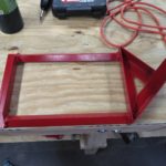
Unlike my last two projects with picture ad nauseum, I’ve picked a small subset for your viewing pleasure. Here’s the CAD profile of the legs for the stand.  These were cut with a water jet from 14 gauge stainless steel.  The circles within the leg are to reduce the overall weight of the leg.  The notch at the base of the leg allows me to easily stake each of the feet.  Some would argue that its to heavy for the application, but the extra weight helps keep the antenna from tipping over without the stakes.  I think its a good balance.

The clamps that hold the legs to the shore pole are 3d printed – as are many other things within my ham radio world.  There’s some 3m double stick tape to keep them in place.

I designed the legs to pivot about the middle clamp so the top hole is drilled to provide clearance for the 8-32 bolt and lock nut that keep them in place.  The top and bottom clamp keep the legs in place.  For these clamps, the legs are tapped instead.  The leg flips to either the deployed position or stowed and an 8-32 bolt is threaded through.  This means that I don’t have to muck with a small fiddly nut in the field.Shot of the “clamps” being printed on my monoprice.   A few shots of the slinky.  One showing how the caps are attached to the slinky, and then a full profile of the single slinky and the double slinky.  I made small retaining straps using elastic and large buttons.  The wire coming out of the bottom is to connect the slinky to the match box.  I did the same sort of arrangement on both stacks of slinkies. Honestly, you don’t need to make it this complicated (in the video up top a simple lanyard clip is used but I always over complicated things. The matchbox.  The banana jacks ordered were to long and were almost touching each other.  I 3d printed some stand offs to try to clean this up.A shot of the mounting horn on the match box.
Found a neat spool on Thingiverse for the counterpoise wire (which per the above table isn’t generally needed).  Printed at 50% x & y, 75% z.


Shack-In-A-Box Mk2 Upgrades: Dimmable Lights, Fans, and Digital Comms

I came up with a few upgrades for my shack in a box:

  1. Integrate a set of Powerpoles into my Samlex power supply for a more aesthetically pleasing connection in the back.
  2. Add speed control/dimmer systems to the fans and lights so that I could control their intensity
  3. Mount my Signalink Digital Interface

These were all a result of working with the shack in a box over the last year. I was hoping to be done in time for the 2019 Field Day but with only one or two days on the weekends I wasn’t able to complete everything in time.  In my defense, the weatherman had predicted 2 days of thunderstorms straight, which is not quite agreeable to electrically charging long metal poles in the sky so I finished up my work on the shack in a box instead. The documentation below is roughly linear.

Build

Wire Guides, Redone

I knew the pwm modules I selected (more later) would require fitting a total of 10 new wires into the existing wire guides. The black ones designed in 2018 were filled to capacity, so I designed and printed some new ones. These were designed as two piece assemblies held together with #2-56 screws. By making the top removable, I saved myself recrimping all the spade connectors for the control panel as well as keeping having to keep the wires straight during reassembly.

Samlex SEC-1235 Anderson PowerPole Mod

Anderson Powerpoles are the defacto standard when it comes to amateur radio power connections.  My “main power feed” into my fused distribution box has powerpoles at the end.  This makes it easy to swap my “feed” between the on board Samlex SEC-1235 or off board batteries or other power sources.  Instead of the ugly “rat’s tail” I had rigged when I first mounted the power supply in November, I wanted to add integrated a set of powerpoles to the onboard Samlex SEC-1235 so it looked like it came that way from the factory.

Bah!

First, I opened up the samlex and pulled the guts out.  Since I would be cutting and filing, removing the internals completely was the easy way to make sure that nothing was fouled as a result. Hardened Power Systems offers the Anderson Autogrip. The idea is to press fit in the powerpoles and have a nice, clean presentation. I mounted them on the autogrip on the inside of the case to further clean the appearance.  The horizontal alignment was picked by finding a free space inside the case before I removed the circuit board and marking it with a sharpie.

After getting the powerpoles into the autogrips and then I reassembled everything and put it back in my mounting rack.  Originally, I intended for the samlex to tuck fully inside and under the bottom shelf.  However, I had some empty wire guides that stopped the samlex from being able to mount that deeply.  While I was swapping to the larger, two piece design I removed the additional wire guides I wasn’t using from the shelf.  This gave me the extra depth I needed to fit the samlex under the shelf, as deeply as I would have liked to originally.

Mounting the PWM Modules

The primary reason for pulling the shack in a box apart this year was to add a way to control the speed of the fans and the brightness of the lights.  I bought some bare PWM Modules from Amazon, knowing I could design and 3d print cases. The legs on the top hold the module down inside of the case.

The cases were designed to also mount the PWM modules to the bottom shelf with a pressed in 8-32 nut. I thought that I would need to hold the lids on with 4-40 screws and included the holes and nut mounts but later decided that the fit was tight enough that the 4-40’s were not needed.

Here is the cura rendering of the box and then lid.

Mounting these was a relatively simple affair, as was connecting the wiring.

Then I needed to mount the rheostats on the control panel for access. I placed some masking tape on the control panel, then put double sided tape on the knobs. I then test fit where the knobs looked the best, and I ended up centering them between the last switch and the USB outlets. I drilled two small 5/32 holes to mark where the knobs would be.

The 3/8″ plywood I used for the switch panel was actually as thick as the overall length of the thread and shaft for the rheostats.  To make it work, I drilled out the front side with a 1/2″ forstner bit.  I need to make some new knobs that would “hide” the deep 1/2″ hole I’d drilled.  A nice, chunky, friendly knob was designed. A small hole was added so that I could press in a small brass brad nail to indicate the position.  The size of the knob hides the 1/2″ hole I drilled, and has a shoulder that presses neatly onto the rheostat’s shaft.

Mounting the Signalink Mount

The last question was how to mount my signalink. I considered mounting it quite a few different ways but decided that I didn’t want to modify the case of the signalink in any way. So I elected to mount it from the face.

Mounting was tricky, but doable. I had to drill two new holes for the faceplate into the shelf. Then, I pushed the 8-32 screws I wanted to use into the bottom holes. The the screws and faceplate were then bolted onto the shelf. I removed the faceplate (and board) from the signalink. Then I pushed the case in from the back. I slid the faceplate and board back in. I printed this with pretty tight tolerances, so I had to push everything in square from all sides. I reattached the faceplate to the case, then used a set of 8-32 screws with washers to make sure that the signalink couldn’t push back on the front.  The faceplate sits on a small shoulder on the mount.

And here’s a demo of the lights and the fans.  I’ll demonstrate the Signalink in a later post.

Note: As before, I have chosen to provide many of the solid model STLs for the 3D Printed Parts I used. However, I provide these STLs without support. I may have suggestions or warnings but they are provided as is. I hope that they are useful to you, but they may not be. Free is free.

Parts

3d Printed

Ordered Parts